
Airflow Visualization – Smoke Studies
Airflow visualization, commonly referred to as smoke studies, is a qualification and verification activity used to demonstrate airflow patterns, airflow direction, and protection of critical zones in controlled environments. Its purpose is to provide direct visual evidence that air movement supports contamination control where it matters.
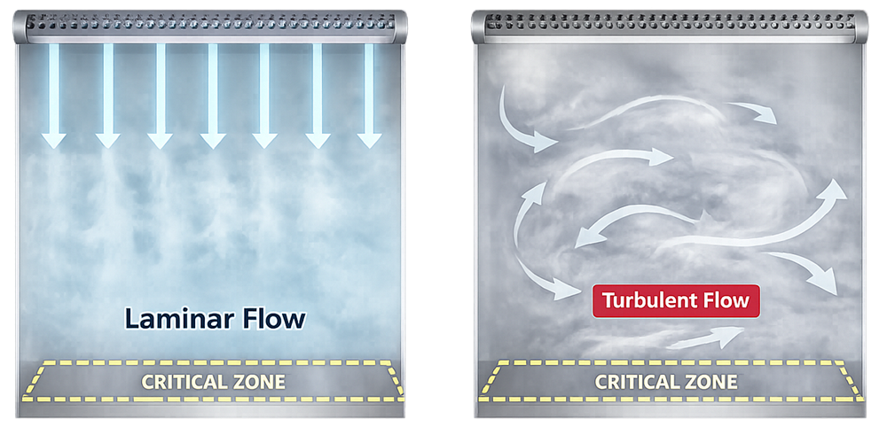
When applied to ISO 5 environments and other critical zones, airflow visualization is a recognized regulatory expectation used to demonstrate that airflow performs as intended and supports contamination control. The diagram below provides a visual comparison of laminar and turbulent airflow patterns commonly observed during smoke studies, highlighting their impact on critical zone protection.
Objectives of Airflow Visualization
A compliant smoke study demonstrates:
- Direction of airflow relative to product and operators
- Unidirectional airflow in ISO 5 zones
- First-air protection of exposed product
- Absence of turbulence, backflow, or stagnation
- Impact of equipment placement and operator movement
- Effectiveness of pressure differentials
Smoke studies are qualitative, but execution must be controlled, repeatable, and documented.
Regulatory Expectation and FDA Inspection Perspective
From a regulatory standpoint, airflow visualization is expected for ISO 5 environments where unidirectional or laminar airflow is assumed by design. This expectation applies to areas where exposed product or critical surfaces rely on first-air protection. Typical examples include:
- Laminar airflow workbenches
- Aseptic processing zones
- Filling lines with exposed product
- Isolators and RABS critical zones
If unidirectional airflow and first-air protection are claimed, FDA expects that claim to be demonstrated, not inferred. In practice, airflow visualization is the accepted method used to provide that demonstration.
U.S. regulations do not mandate smoke studies by name. Instead, they require manufacturers to demonstrate that facility design, ventilation, and airflow systems adequately prevent contamination and protect product. During FDA inspections, the absence of airflow visualization in ISO 5 areas is routinely cited as a deficiency in demonstrating control of aseptic processing, particularly where airflow performance is assumed but not verified.
Airflow visualization is not limited to ISO 5 environments and is commonly applied as a risk-based tool in other classified or controlled areas to explain airflow behavior, support investigations, and verify the effectiveness of corrective actions including:
- ISO 7 and ISO 8 cleanrooms with complex airflow patterns
- Gowning rooms supporting aseptic operations
- Weighing and dispensing areas
- Areas with recurring environmental monitoring excursions
- Rooms following HVAC modifications or CAPAs
The regulatory basis for these expectations is established through the following requirements, which mandate airflow control and demonstrable performance without prescribing a specific test method:
- 21 CFR 211.42 – Facility design to prevent contamination
- 21 CFR 211.46 – Adequate air filtration, ventilation, and airflow performance
- FDA Aseptic Processing Guidance – Expectations for first air, unidirectional airflow, and critical zone protection
- EU GMP Annex 1 – Airflow pattern control as part of contamination control strategy
- ISO 14644 – Cleanroom classifications and performance assumptions dependent on controlled airflow
If airflow matters to product quality, FDA expects you to understand it. Airflow visualization is how that understanding is proven.
Airflow Visualization Examples
The following examples illustrate typical airflow behaviors observed during smoke studies, ranging from compliant unidirectional airflow to localized turbulence and controlled airflow delivery methods.
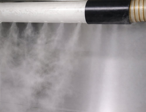
Smoke Manifold Example
A perforated manifold provides evenly distributed smoke release across the airflow face, supporting consistent visualization of airflow uniformity and identifying localized disturbances.
Laminar Flow Example
Smoke streams descend in parallel, vertical paths with no lateral drift or reflux, demonstrating unidirectional airflow and effective first-air protection of the critical zone.
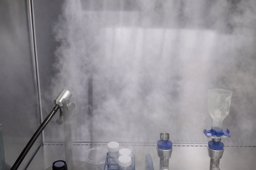
Local Protection Zone (LPZ) Example
Smoke visualization demonstrates localized protection within an ISO 5 hood, where airflow is directed to protect a local protection zone rather than the entire enclosure.
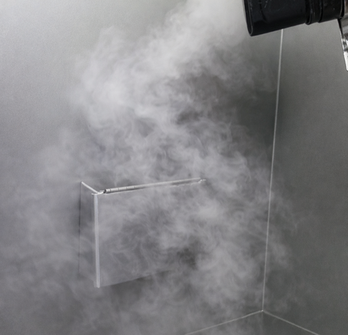
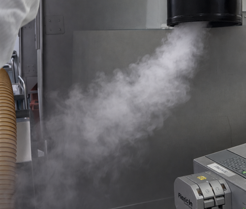
Smoke Turbulence Example
Smoke shows lateral movement and swirling patterns, indicating airflow disruption and loss of unidirectional behavior. This condition would require investigation and corrective action in an ISO 5 zone.
Airflow Visualization Equipment
Vaporized Glycol or Glycerin Systems
These systems are widely used but not ideal in GMP environments. They may be acceptable, but they are rarely the best choice in critical areas. Key drawbacks:
- Leave residues on surfaces and HEPA faces
- Introduce cleaning and requalification challenges
- Often require post-study cleaning justification
- Can complicate deviation investigations if residues are detected
Liquid Nitrogen and Cryogenic Fog
- Produces dense, neutrally buoyant visible fog
- No chemical residue
- Dissipates cleanly
- Highly effective for large rooms and dynamic studies
Operational controls are required, but from a contamination standpoint, this is a cleaner solution.
Dry Ice Fog
- Generates visible CO₂ fog without residue
- Suitable for room-level airflow and pressure visualization
- Simple, effective, and regulator-friendly
Care must be taken with ventilation and personnel safety, but cleaning concerns are minimal.
Water-Based Fog Systems
- Use deionized or purified water
- No glycol or glycerin residues
- Compatible with GMP cleaning programs
These systems align well with pharmaceutical cleaning expectations.
Professional judgment, based on audits and remediation work:
If you want fewer questions from QA and fewer headaches after the study, avoid glycol and glycerin unless there is a strong justification.
Practical Application Examples
Airflow visualization is commonly applied in the following controlled scenarios:
- ISO 5 laminar airflow areas
Verification of unidirectional airflow and first-air protection over exposed product and critical surfaces. - Aseptic processing operations
Confirmation that airflow remains protective during defined operator interventions and routine activities. - ISO 7 and ISO 8 cleanrooms
Evaluation of airflow behavior where diffuser layout, equipment placement, or monitoring data indicates potential turbulence. - Gowning rooms and pressure transitions
Confirmation of airflow direction during door openings and personnel movement to support pressure cascade design.
Video recording using fixed or installed cameras is preferred over handheld recording, as it provides controlled, time-stamped, and reviewable evidence suitable for inspection and long-term retention.
Documentation and Execution Expectations
A defensible airflow visualization program includes:
- Approved protocol with defined objectives
- Defined conditions such as at-rest and dynamic
- Controlled smoke generation method
- Video recording with date, time, and location identifiers
- Clear conclusions tied to acceptance criteria
- Integration with HVAC qualification or environmental control strategy