
Airflow, Filtration, and Pressure Verification
This article lays out a field-ready approach to verifying airflow performance, HEPA filter integrity, and room pressure relationships, with enough detail that an engineer can execute, document, and defend the work. The mindset is simple. Measure what matters, use recognized methods, record raw data, and produce calculations that a reviewer can reproduce.
1. Prerequisites and set-up
Before you take a single reading, lock down the conditions. Most “bad data” comes from sloppy setup, not bad instruments.
Facility conditions
- System in normal operating mode, not commissioning or manual override
- Doors in their intended state for operation, typically closed for classified rooms
- People minimized during measurements, especially for particle work
- Confirm stable operation for a reasonable period, commonly 15 to 30 minutes
Instrumentation expectations
Use calibrated instruments with current certificates. Record instrument ID, model, range, and calibration due date in the data sheet. At minimum:
- Balometer or flow hood for diffusers and grilles
- Hot-wire anemometer or vane anemometer for face velocity work
- Micromanometer for differential pressure
- Aerosol photometer and aerosol generator for HEPA integrity testing
- Non-viable particle counter for ISO classification support
2. Airflow verification
Airflow verification has three deliverables that matter in GMP. Supply and return quantities, directional intent, and air exchange rate.
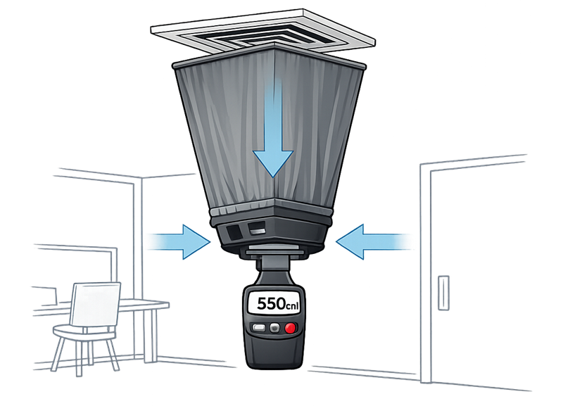
2.1 Measuring airflow at supply diffusers and returns
Preferred technique
- Use a flow hood over each diffuser or grille where geometry allows. This is the most straightforward, repeatable approach.
- For linear slots, perforated plates, or awkward outlets, use velocity traverse and calculate flow.
Velocity traverse method
- Measure velocity at multiple points across the opening.
- Use an average velocity and multiply by the free area.
Basic calculation
- Flow, CFM = Average velocity, FPM × Area, ft²
- If your instrument outputs in m/s, convert consistently before calculating.
Execution discipline
- Take at least 3 readings per point where stability is questionable.
- Record raw readings, not just averages.
- Document diffuser ID and location with a markup drawing or room map.
2.2 Airflow direction and qualitative confirmation
Airflow direction is not proven by numbers alone. You confirm direction using a combination of:
- Pressure cascade verification
- Smoke visualization at door bottoms and transfer points
- Observation of “push” at openings during door cracks
Keep smoke work short and controlled. The purpose is directional confirmation and identification of gross turbulence, not theater.
3. Air exchange rate calculation
Air exchange rate is one of the most misreported values in field qualification. The only defensible approach is to tie it to measured airflow and room volume.
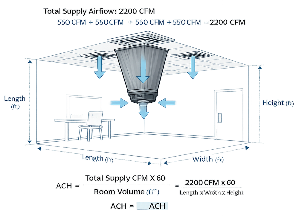
3.1 Method
- Determine room volume
- Volume, ft³ = Length × Width × Height
- Use as-built dimensions. Document source.
- Determine total supply airflow into the room
- Sum measured CFM from all supply diffusers serving the room.
- Calculate air changes per hour
- ACH = (Total supply CFM × 60) ÷ Room volume, ft³
3.2 Practical notes
- Use supply CFM, not return CFM, unless the room is exhaust-driven and designed that way.
- If significant exhaust exists, document it separately and reconcile supply–return–exhaust balance.
- If doors are frequently opened during operations, consider a separate “operational observation” note, but keep the qualification baseline in controlled conditions.
4. HEPA filter integrity testing
If the room classification or risk assessment requires terminal HEPA filters, integrity testing is not optional. It is the cornerstone evidence that filtration actually works.
HEPA Filter Integrity Testing – Aerosol Challenge and Downstream Scan
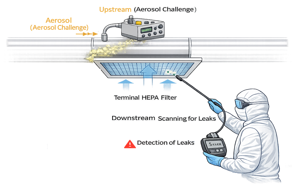
4.1 Standard field approach
A common field method is aerosol challenge upstream and photometer scanning downstream to detect leaks.
Core steps
- Verify filter installation, frame integrity, and gasket seating
- Establish an upstream aerosol concentration
- Zero the photometer and perform reference checks
- Scan the downstream face and perimeter at a controlled probe speed
- Identify and quantify leaks and document exact locations
- Repair and retest any failed areas
- Record final pass status and baseline pressure drop
4.2 Technique points that matter
- Upstream sampling location must represent uniform mixing. If it does not, your test is invalid.
- Scan pattern must cover the full face and critical seals, not just a few passes.
- Probe distance and speed must be consistent. Too fast hides leaks.
- Document aerosol type, generator settings, photometer settings, and challenge concentration.
4.3 Documentation deliverables
- Filter ID and location
- Pass or fail criteria used
- Upstream concentration and method of verification
- Leak map with photo or sketch
- Repairs performed and retest results
- Final differential pressure across the filter
5. Differential pressure verification
Differential pressure is a primary control for segregation. Treat it like a safety interlock, not a comfort parameter.
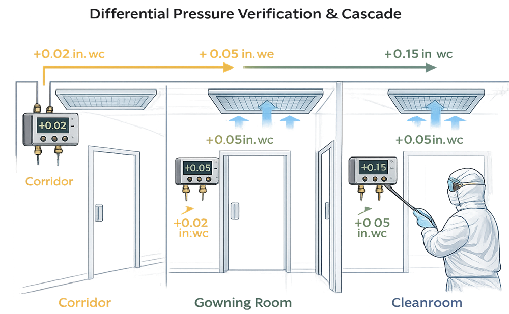
5.1 Measurement technique
Reference method
- Use a calibrated micromanometer.
- Measure across each defined boundary in the pressure cascade.
Where to measure
- Across doors between classified areas
- Across gowning transitions
- Across critical room boundaries, including airlocks and pass-throughs
Good practice
- Verify pressure with doors closed, then check behavior during a controlled door opening.
- If permanent pressure transmitters exist, compare transmitter display to your reference instrument and document the difference.
5.2 Alarms and control checks
- Verify alarm setpoints match approved design and SOP expectations
- Simulate a loss of differential pressure where practical
- Confirm local indication, BMS trending, and alarm annunciation pathways
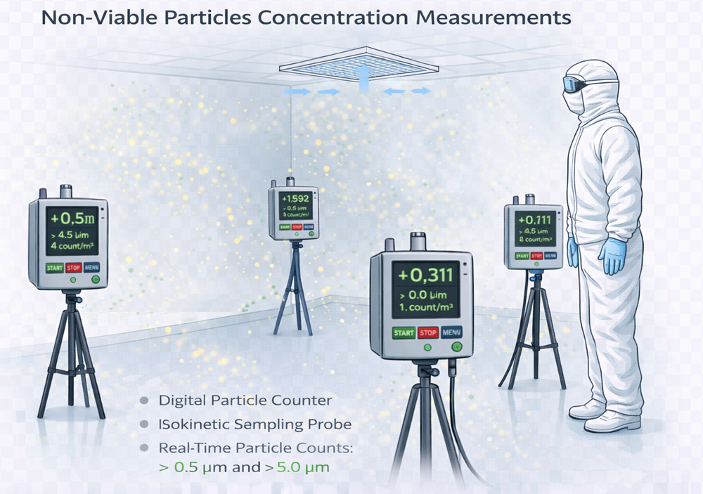
6. Non-viable particle testing
Particle counts define ISO classification. This is not “nice to have” if the room is claimed as ISO 8, ISO 7, or ISO 5 and the airflow and HEPA work should be planned with particle performance in mind.
Practical link to airflow verification
- Airflow and filtration create the conditions that allow the particle classification to pass.
- If ACH is weak, diffuser distribution is poor, or HEPA integrity is questionable, particle results will be unstable and you will chase failures.
Key execution notes
- Use a calibrated particle counter and record: flow rate, sample volume, locations, and room condition
- Define “at rest” vs “operational” clearly and do not mix them in the same acceptance table
- Establish sampling locations tied to risk. Not “pretty evenly spaced,” but “where product and exposure risk exist.”
7. Typical acceptance structure
A practical acceptance package usually includes:
- Airflow quantities per diffuser and room totals
- ACH calculations by room
- Differential pressure readings per boundary and cascade verification
- HEPA integrity results per filter with leak maps
- Particle counts supporting ISO classification, where required
Acceptance criteria must be defined in advance and tied to URS and the facility contamination control strategy. “Pass because it looks fine” is not a regulated approach.
8. Common failure modes and how to avoid them
These show up repeatedly in the field:
- ACH reported without measured airflow
- Pressure cascade “assumed” from design, not measured
- HEPA scan performed too fast or without credible upstream challenge
- Particle sampling locations picked for convenience
- No reconciliation of supply vs return vs exhaust
If you avoid these, your verification package will hold up in QA review and during inspections.