
Aseptic Filling Line Architecture
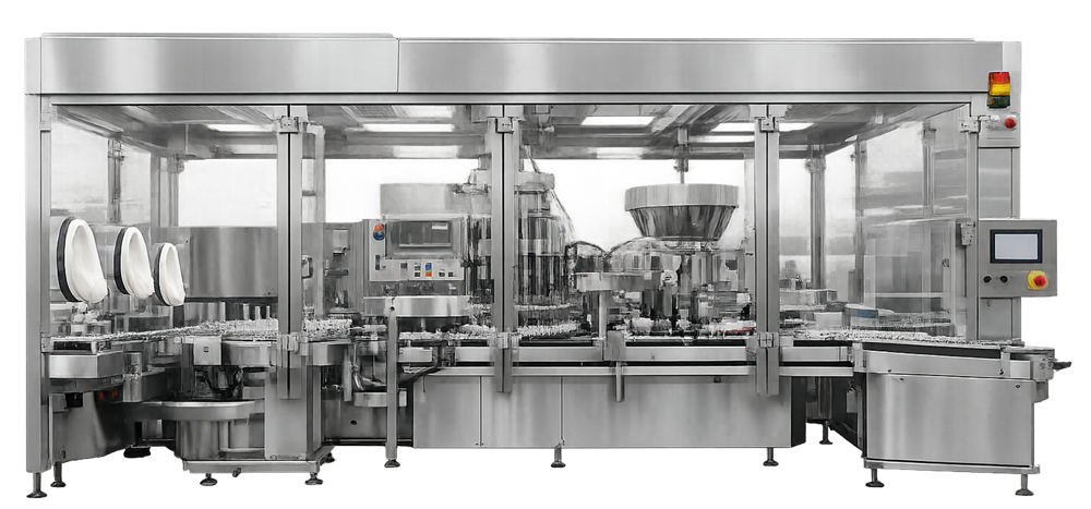
Aseptic filling line architecture defines the mechanical and functional configuration required to transfer sterile product into final containers while maintaining sterility at every critical exposure point. The filling line does not operate in open space. It is installed within an ISO 5 environment, typically achieved through an isolator or RABS system, which provides controlled unidirectional airflow over exposed sterile components and open containers.
While barrier technology and environmental control are addressed in a separate article, the filling line must be designed to function within that ISO 5 protection strategy. Mechanical layout, intervention access, and airflow exposure points must be aligned with the barrier design.
The objective of the architecture is to preserve sterility during filling and initial closure while ensuring mechanical reliability, process consistency, and validation control.\
1. Overall Line Configuration
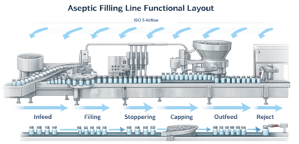
A typical aseptic filling line consists of multiple mechanically and logically integrated subsystems. Each performs a defined function within the overall sterility assurance strategy.
Container Infeed and Accumulation
The infeed system transfers sterilized containers into the filling line while maintaining orientation, spacing, and stability. Containers may enter from a depyrogenation tunnel, sterilization transfer system, or bulk feed accumulation table.
Primary functions include:
• Controlled container spacing prior to filling
• Prevention of container tipping or collision
• Elimination of glass-to-glass contact
• Synchronization with downstream machine speed
Timing screws or star wheels regulate container pitch and dwell time. Accumulation zones must prevent pressure buildup that could cause microcracks or cosmetic damage. The infeed must maintain smooth transfer into the ISO 5 exposure zone without creating turbulence or mechanical vibration.
Filling Station
The filling station meters sterile product into each container with defined accuracy and repeatability. It includes:
• Filling needles or nozzles
• Metering mechanism
• Product manifold
• Drip control devices
Needles are positioned to deliver product without splashing or foaming. In many systems, bottom-up filling reduces aerosol formation and surface agitation. The metering system controls delivered volume using time-pressure regulation, peristaltic displacement, piston stroke control, or mass flow measurement.
The filling station must maintain:
• Precise vertical and lateral needle alignment
• Consistent insertion depth
• Controlled product pressure
• Accurate synchronization with container indexing
Any deviation can result in underfill, overfill, or mechanical contact with the container.
Stopper Insertion System
After filling, sterile elastomeric stoppers are positioned onto or into the container. The stoppering mechanism typically includes:
• Sterile stopper bowl or feed system
• Orientation track
• Insertion head or plunger mechanism
The system ensures that each stopper is correctly oriented and inserted with controlled force. In liquid filling operations, full seating is required prior to capping. In lyophilization processes, partial insertion is required to allow vapor escape during drying.
Insertion force must be sufficient to secure placement without causing deformation or rebound. Inconsistent stoppering may compromise container closure integrity.
Capping or Crimping Station
The capping station secures the stopper using an aluminum seal or alternative closure component. It typically includes:
• Cap feeder and orientation system
• Crimping head
• Force adjustment mechanism
• Inspection sensors
Crimp force and skirt formation must be controlled to ensure proper compression of the stopper without damaging the container. Excessive force may deform the closure system, while insufficient force may result in inadequate seal retention.
Although capping may occur outside the immediate open-container exposure zone, it directly affects long-term closure integrity and product stability.
Outfeed Conveyor
The outfeed system transports filled and closed containers to downstream processes such as visual inspection or labeling.
Its functions include:
• Smooth container discharge
• Controlled spacing
• Integration with inspection or rejection systems
• Prevention of mechanical shock
Improper outfeed design can introduce vibration that compromises stopper seating prior to crimp stabilization.
Integrated Reject Mechanisms
Reject systems automatically remove containers that do not meet predefined criteria. These criteria may include:
• Fill volume deviation
• Missing stopper
• Improper stopper position
• Crimping defects
• Container misalignment
Rejection mechanisms must be mechanically reliable and synchronized with indexing. Improper rejection can result in nonconforming units remaining in the batch or unnecessary product loss.
System Integration and Exposure Control
The filling, stoppering, and any open-container exposure steps occur under ISO 5 conditions. Mechanical structures, drive assemblies, and framing must be positioned so they do not interfere with unidirectional airflow protecting critical zones.
The line must operate as an integrated system. Indexing speed, needle actuation, stopper placement, and rejection timing are interdependent. Loss of synchronization can cause container exposure, misalignment, or interruption of first air protection.
Architectural design therefore requires coordinated mechanical engineering and sterility risk control. The filling line is not a collection of machines but a unified system designed to preserve sterility through controlled motion, precise timing, and stable ISO 5 exposure conditions.
2. Installation Within ISO 5 Environment
The filling line is physically installed inside a barrier system that provides ISO 5 conditions at the point of product and component exposure. This typically includes:
• Unidirectional airflow over open vials
• HEPA-filtered air supply
• Defined critical exposure zones
• Controlled intervention access
The mechanical architecture of the line must support airflow stability. Obstructions, excessive structural members, or poorly positioned drive assemblies can create turbulence and compromise protection.
Access points for maintenance or setup must be engineered so they do not introduce uncontrolled exposure during operation.
3. Container Handling and Transport
Container transport mechanisms include timing screws, star wheels, indexing turrets, and servo-driven conveyors. These components control container positioning and dwell time at the filling needles.
Mechanical precision is essential. Misalignment can result in:
• Needle collision
• Fill variability
• Container tipping
• Particle generation
All moving components located within ISO 5 must be constructed to minimize friction and shedding. Container accumulation must prevent glass-to-glass contact that can generate particulates.
4. Filling System Design
The filling system is the central functional element of the line. Selection of filling technology affects fill accuracy, product integrity, and validation complexity.
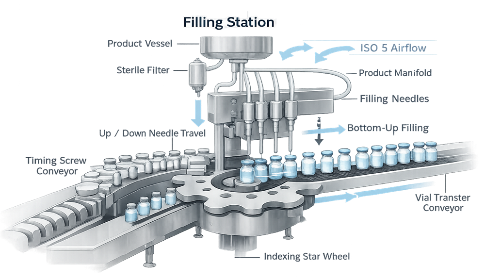
The diagram below illustrates the critical filling zone of the aseptic line, highlighting the product delivery pathway, needle alignment, and container indexing mechanism. This area represents the primary sterile exposure point where open containers receive product under ISO 5 conditions. Mechanical precision and airflow stability at this location are essential to prevent contamination, splashing, and fill variability.
Common filling approaches include:
• Time-pressure systems
• Peristaltic pump systems
• Rotary piston systems
• Mass flow–controlled systems
Peristaltic systems restrict product contact to disposable tubing and needles. Time-pressure systems require stable viscosity and pressure control. Mass flow systems provide high precision but require validated calibration and control logic.
Critical design parameters include:
• Needle positioning and insertion depth
• Bottom-up filling to reduce foaming
• Drip control
• In-process fill verification
• Automatic rejection of nonconforming units
Fill accuracy must be demonstrated under operational speed within the ISO 5 environment.
5. Sterile Product Pathway
The sterile product pathway includes the holding vessel, transfer tubing, sterile filtration assemblies, manifolds, and filling needles. Architectural controls must address:
• Drainability
• Elimination of dead legs
• Pressure stability
• Integrity testing capability
Filter housings must support pre-use and post-use integrity testing. Tubing configuration should minimize hold-up volume and exposure duration. Where single-use assemblies are used, configuration control and supplier sterilization validation become integral architectural considerations.
6. Stoppering and Initial Closure
After filling, sterile stoppers are positioned on the container under ISO 5 conditions. For liquid products, stoppers are typically fully seated before capping. For lyophilized products, stoppers are partially inserted prior to transfer to the freeze dryer.
Stopper delivery systems must provide consistent orientation and controlled insertion force. Mechanical variability can affect:
• Container closure integrity
• Vacuum stoppering performance
• Sterility assurance
Stopper placement occurs within the ISO 5 exposure zone and must not disrupt airflow protection.
7. Capping and Sealing Systems
Capping stations apply aluminum seals or alternative closure mechanisms. Depending on configuration, capping may occur within or adjacent to the ISO 5 zone. Design considerations include:
• Controlled crimp force
• Cap alignment
• Vibration control
• Detection and rejection of improperly sealed units
Mechanical force must be sufficient to secure closure without compromising stopper compression.
8. Automation and Control Architecture
Modern filling lines incorporate integrated control systems managing sequencing, alarms, and data capture.Control architecture typically includes:
• PLC-based machine control
• Recipe management
• Alarm and interlock logic
• Fill monitoring systems
• Reject tracking
Interlocks must prevent operation outside validated limits. Control logic must coordinate with the barrier system to avoid unintended exposure during startup, intervention, or shutdown.
Where electronic data are captured, system design must support secure access, audit trail functionality, and validated data handling.
9. System Interfaces
Aseptic filling lines interface with:
• Component washing and depyrogenation systems
• Sterilization systems
• Lyophilizers where applicable
• Inspection and packaging equipment
Each interface represents a potential sterility risk boundary. Transfer points must be defined and controlled during design qualification.
10. Architectural Risk Drivers
The diagram below identifies the primary architectural risk zones within an aseptic filling line. It overlays mechanical, airflow, and control-related vulnerabilities directly onto the functional layout of the system. These highlighted areas represent points where sterility assurance may be compromised if design, alignment, synchronization, or environmental stability are not properly controlled and qualified.
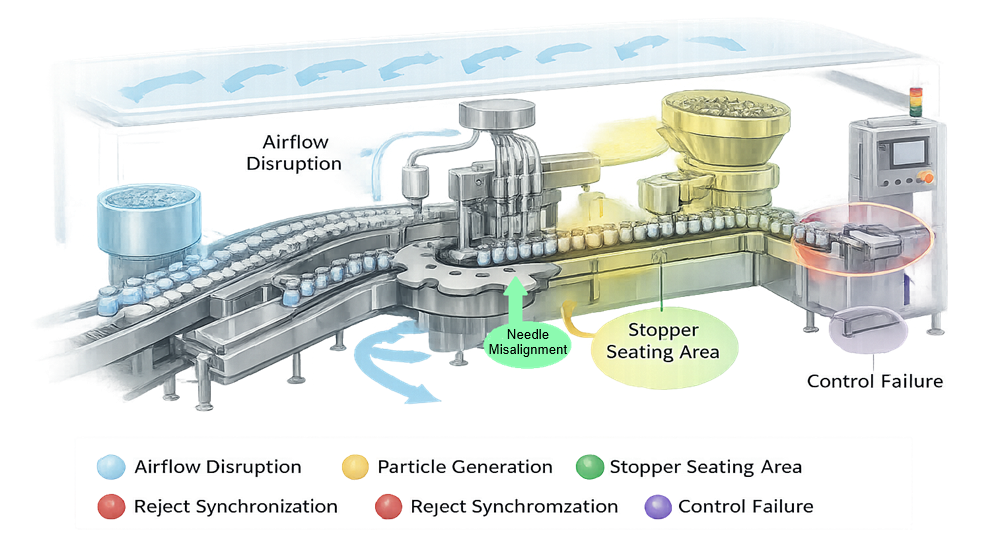
Primary architectural risks include:
Disruption of ISO 5 first air
Unidirectional airflow over open containers and sterile components is the primary contamination control mechanism. Structural obstructions, poorly positioned drive components, excessive vibration, or improperly designed intervention access can create turbulence or airflow shadowing. Even localized disturbance at the needle tip or stopper placement point increases exposure risk during critical operations.
Mechanical particle generation
Moving components such as star wheels, timing screws, guide rails, and crimping heads can generate particles through friction, wear, or impact. Glass-to-glass contact, stopper abrasion, and cap deformation are additional sources. Particle generation within the ISO 5 zone directly increases contamination probability and must be minimized through material selection, alignment precision, and preventive maintenance design.
Needle misalignment
Improper vertical or lateral positioning of filling needles can result in container contact, splashing, or incomplete insertion depth. This may cause aerosol formation, product droplet dispersion, or glass chipping. Needle deflection under speed or vibration is a mechanical risk that must be addressed during design and qualification.
Improper stopper seating
Inconsistent insertion force, stopper orientation errors, or mechanical rebound can result in incomplete seating. For lyophilized products, improper partial insertion may interfere with vapor escape or vacuum stoppering. For liquid products, inadequate seating compromises container closure integrity and sterility assurance.
Inadequate reject detection
Failure to reliably detect and remove underfilled units, missing stoppers, or crimp defects allows nonconforming containers to proceed downstream. Reject logic must be synchronized with container indexing and verified under production speed. Architectural design must ensure reject mechanisms function without disrupting airflow or adjacent containers.
Control system malfunction
Loss of synchronization between indexing, filling, stoppering, and capping can create uncontrolled exposure events. Sensor failure, improper interlock logic, or software error may allow operation outside validated parameters. Control architecture must enforce sequencing, alarm handling, and defined safe states.
These architectural factors determine the depth of qualification, the design of airflow studies, the scope of media fill simulation, and the structure of environmental monitoring. High-risk mechanical zones require targeted verification during OQ and representation in process simulation studies.
Aseptic filling line architecture therefore establishes the structural and mechanical foundation upon which sterility assurance is demonstrated. Without a controlled architectural design operating within a validated ISO 5 environment, contamination control cannot be reliably achieved or sustained.