
Bioreactor Qualification
1. Introduction
Bioreactor qualification establishes documented evidence that a bioreactor system is fit for its intended use and capable of maintaining controlled, reproducible biological processing conditions within predefined limits. In regulated pharmaceutical manufacturing, bioreactors are direct-impact systems. Their performance directly influences critical process parameters, sterility assurance, product quality attributes, and batch record reliability.
Qualification is not limited to confirming mechanical installation. It must demonstrate that the system design, instrumentation, sterilization capability, control architecture, and operational performance collectively support validated process control. The qualified state must then be maintained throughout the equipment lifecycle.
This article presents a comprehensive, engineering-focused qualification approach suitable for GMP seed reactors, pilot-scale systems, and production stainless-steel bioreactors. Detailed computerized system validation is addressed separately; however, control system functionality relevant to equipment qualification is included.
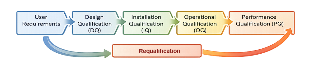
The diagram below presents the linear lifecycle model for bioreactor qualification, illustrating the structured progression from defined user requirements through qualification phases, continued verification, and requalification, with formal feedback into updated requirements when changes or deviations occur.
2. Qualification Strategy and System Boundary Definition
A clear system boundary is essential before protocol development. A bioreactor system typically includes:
- Vessel and internal components such as impellers, baffles, spargers
- Agitation drive and mechanical seals
- Gas train including filters, mass flow controllers, regulators
- Feed and addition systems
- Sampling assemblies
- Exhaust filtration
- CIP circuits and spray devices
- SIP circuits and steam interfaces
- Instrumentation and transmitters
- Control system hardware and interface
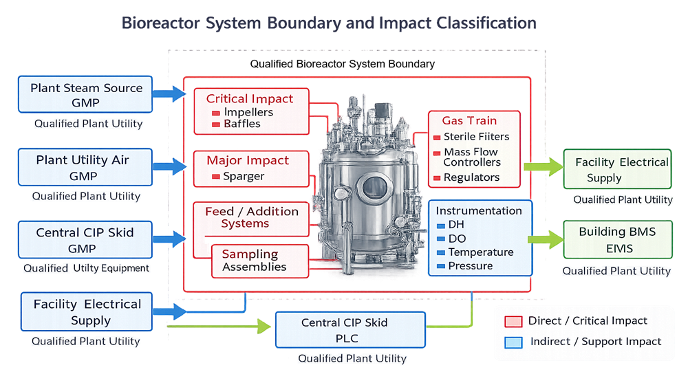
The boundary must specify which elements are included in qualification and which are managed under separate utility or facility qualification programs. The diagram below defines the bioreactor system boundary for qualification purposes, identifying components included within the qualified scope and distinguishing direct-impact elements from external plant utilities and support systems managed under separate programs.
A formal risk assessment should classify components as direct-impact or indirect-impact based on potential effect on product quality, sterility, or critical parameter control. This classification determines qualification depth and testing rigor.
3. User Requirements and Design Qualification
3.1 User Requirements Specification
The URS defines functional expectations and must precede qualification. It should include:
- Working volume and geometric configuration
- Material of construction and surface finish requirements
- Operating pressure and temperature ranges
- Agitation range and impeller configuration
- Gas handling capability and oxygen transfer expectations
- CIP and SIP capability and required parameters
- Sensor types and accuracy requirements
- Alarm and interlock expectations
- Data acquisition and retention requirements
All acceptance criteria later used in IQ, OQ, and PQ must trace back to defined requirements.
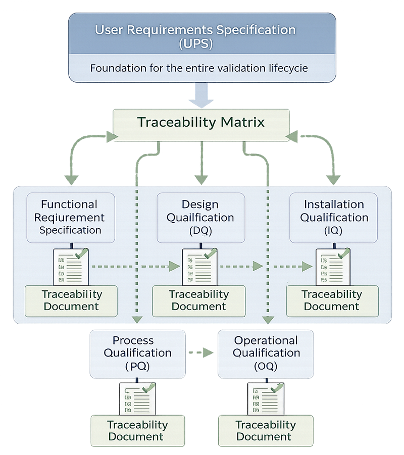
The diagram below illustrates the URS traceability concept, showing how documented user requirements form the foundation of the validation lifecycle and are mapped through a structured traceability matrix into qualification activities. Each requirement must be linked to specific design elements and corresponding verification tests within DQ, IQ, OQ, and PQ to ensure that all expectations are formally addressed and objectively verified. Bidirectional traceability ensures that every qualification test can be traced back to a defined requirement and that no requirement remains unverified.
3.2 Design Review
Design Qualification confirms that the selected equipment meets URS expectations. Review includes:
- P&ID evaluation
- Instrument list and measurement ranges
- Surface finish and weld documentation
- Elastomer compatibility
- Drainability and dead-leg risk
- Steam distribution and condensate removal strategy
- Gas filter positioning and integrity testing provisions
Traceability between URS clauses and design elements must be documented.
3.3 Design Risk Assessment
Design-phase risk assessment identifies vulnerabilities such as:
- Inadequate steam penetration
- Cold spots during SIP
- Excessive dead legs
- Sensor placement in stagnant zones
- Foam carryover into exhaust filters
- Seal leakage under agitation
These risks define OQ challenge scenarios and PQ focus points.
4. Installation Qualification
Installation Qualification verifies that the system is installed in accordance with approved design and manufacturer specifications.
4.1 Equipment Identification
Document:
- Equipment tag and serial number
- Model and manufacturer
- Installation location
- Associated documentation set
4.2 Mechanical Verification
Confirm:
- Vessel leveling and support integrity
- Correct installation of impeller and shaft
- Mechanical seal condition
- Valve orientation and labeling
- Proper assembly of internal components
- Accessibility for maintenance
4.3 Materials and Surface Finish
Verify:
- Material certificates for product contact surfaces
- Surface finish compliance
- Elastomer material suitability
- Weld documentation where applicable
4.4 Utilities Verification
Confirm utility connections and capacity:
- Electrical supply
- Instrument air
- Process gases
- Steam quality and pressure
- Cooling water or glycol
- Drain routing
Utility inadequacy frequently manifests as operational instability.
4.5 Instrumentation and Calibration
Verify:
- Installation of sensors
- Correct range configuration
- Calibration status and traceability
- Alarm setpoint baseline
Configuration of transmitters and scaling must match design intent.
5. Operational Qualification
Operational Qualification demonstrates that the bioreactor performs as intended across defined operating ranges. Acceptance criteria must be:
- Scientifically justified
- Defined prior to execution
- Traceable to URS
- Based on process risk
5.1 Agitation Performance
Verify:
- Minimum and maximum speed capability
- Stable operation without abnormal vibration
- Seal performance under dynamic load
Where applicable, confirm mixing time at representative conditions.
5.2 Temperature Control
Challenge:
- Stability at setpoint
- Response to step changes
- Overshoot behavior
- Alarm activation at deviation limits
If multiple sensors are installed, confirm agreement within defined tolerance.
5.3 pH Control
Verify:
- Calibration accuracy
- Stable control under controlled acid/base additions
- Alarm responses
- Absence of sustained oscillation
5.4 Dissolved Oxygen Control
Confirm:
- Sensor stability
- Cascade control logic functionality
- Ability to maintain setpoint under increasing demand
- Alarm and limit responses
5.5 Gas and Pressure Systems
Verify:
- Backpressure stability
- Flow control functionality
- Proper gas routing
- Filter housing integrity
5.6 CIP Functional Verification
Demonstrate:
- Spray device coverage rationale
- Cleaning solution flow and pressure
- Drainability
- Control logic execution
Cleaning acceptance limits for residues are often confirmed during process validation; OQ confirms system capability.
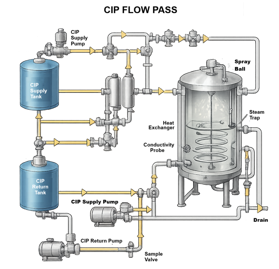
The diagram below illustrates the Clean-in-Place flow path for a bioreactor system, showing the controlled circulation of cleaning solution from the CIP supply tank through pumps, heat exchanger, valves, and spray devices into the vessel, followed by drainage and return through the designated outlet and monitoring points. During the CIP cycle, solution temperature, flow rate, chemical concentration, and contact time are maintained within predefined parameters to ensure effective coverage of all product-contact surfaces. Recirculation continues for the defined duration before discharge or return, demonstrating that the system is capable of consistent and reproducible cleaning performance.
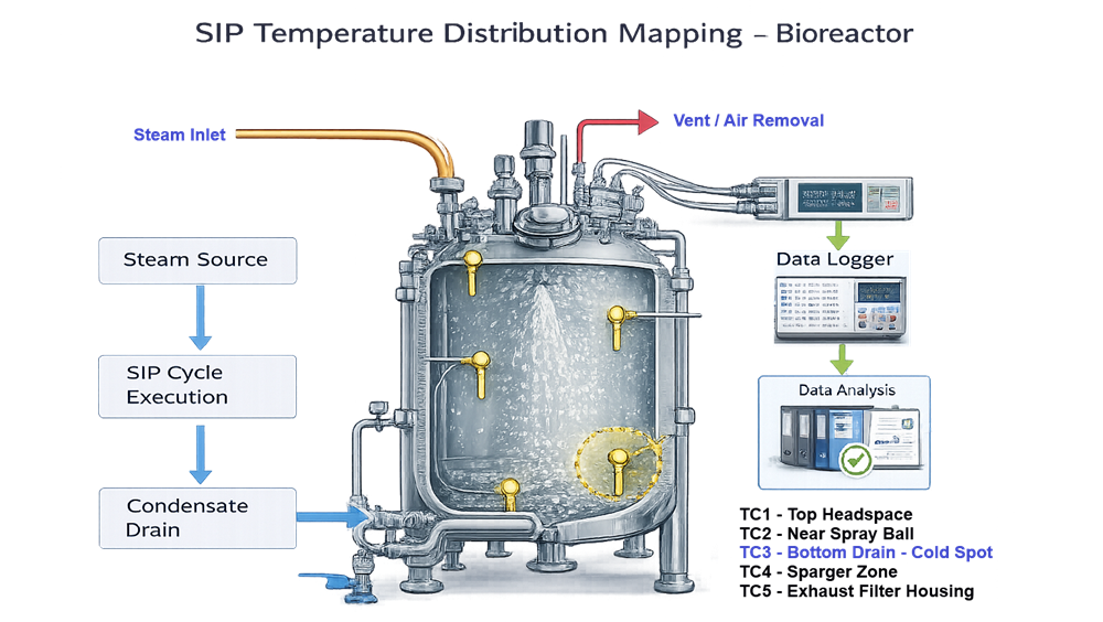
5.7 SIP Functional Verification
SIP is critical for sterile applications.
Verify:
- Achievement of minimum sterilization temperature
- Hold time compliance
- Temperature distribution and identification of cold spot
- Air removal and condensate management
- Post-SIP pressure integrity
Worst-case locations must be defined and justified.
Technical diagram showing the qualified bioreactor system boundary with internal components including vessel, impellers, baffles, gas train, feed systems, CIP and SIP circuits, instrumentation, and control system, and external utilities such as plant steam, utility air, electrical supply, and building systems located outside the qualification boundary.
5.8 Alarm and Interlock Testing
Verify:
- Correct setpoints
- Proper annunciation
- Logging accuracy
- Safe-state transitions
Critical alarms include temperature deviation, agitation failure, loss of gas supply, and high pressure.
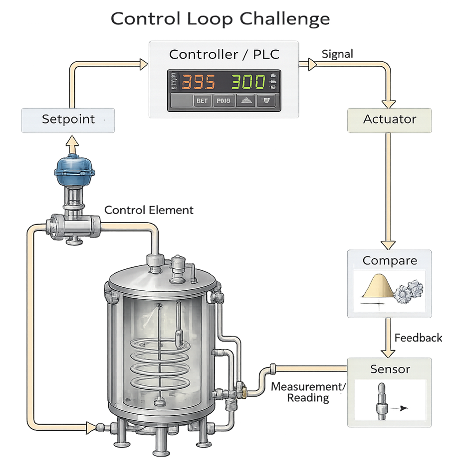
The diagram below illustrates the control loop challenge concept used during Operational Qualification to verify that the bioreactor control system responds predictably to setpoint changes and controlled disturbances. A loop challenge evaluates the complete closed-loop system, including setpoint input, controller logic, actuator response, process behavior, sensor measurement, and feedback comparison. During testing, defined adjustments or disturbances are introduced to confirm that the controller drives the actuator appropriately, the process variable responds within predefined acceptance limits, overshoot and stabilization time remain controlled, and the measured value accurately reflects actual conditions. The objective is to demonstrate stable, repeatable control performance across dynamic operating conditions, ensuring that critical process parameters can be maintained within validated ranges.
6. Performance Qualification
Performance Qualification confirms that the bioreactor performs reproducibly under representative operating conditions.
The diagram below illustrates the concept of Performance Qualification reproducibility, demonstrating that critical process parameters remain within predefined acceptance criteria across multiple consecutive PQ runs. Consistent control behavior across these runs provides evidence that the bioreactor system can sustain stable and repeatable operation under validated conditions.
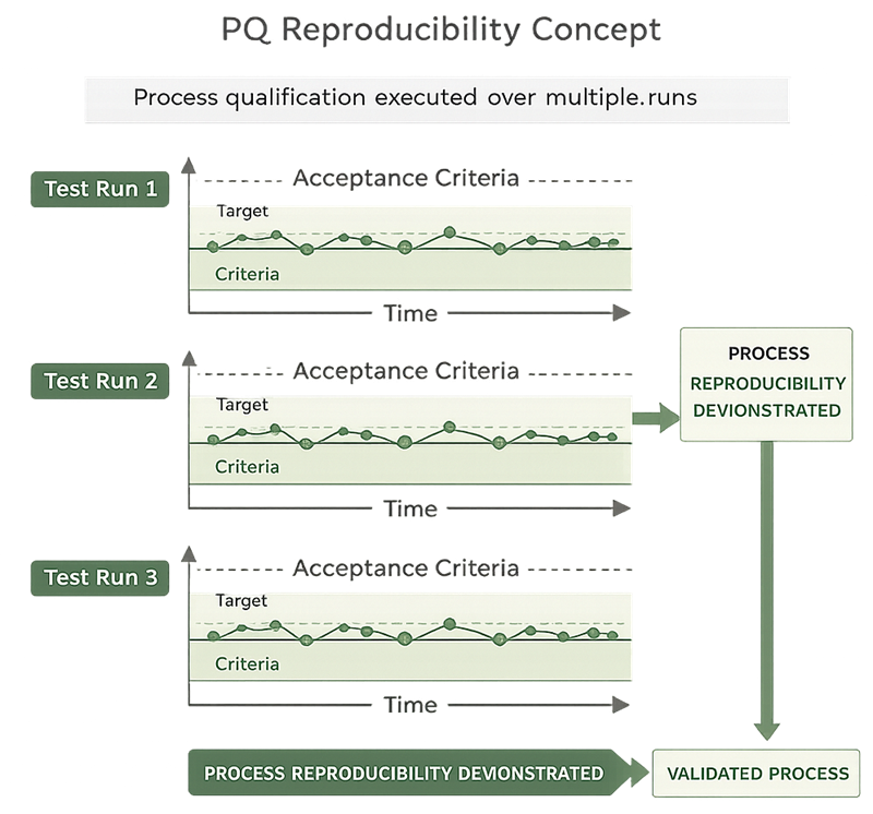
6.1 PQ Design
PQ should include:
- Representative process configuration
- Defined batch size
- Defined parameter setpoints
- Defined acceptance criteria
Multiple consecutive runs are typically executed to demonstrate reproducibility.
6.2 Control Stability
Confirm:
- Stable control of CPPs
- Absence of unexplained excursions
- Consistent sensor behavior
- Stable agitation and gas flow
6.3 Sterile Operation Performance
For sterile systems, confirm:
- Aseptic additions function correctly
- Sampling maintains sterility
- Exhaust filters remain protected
- Transfer operations maintain boundary integrity
Where media fills are required, they are executed under separate aseptic process validation programs.
7. Equipment Qualification vs Process Validation
Equipment qualification demonstrates that the bioreactor can maintain defined environmental and control conditions.Process validation demonstrates that, Clear separation between Equipment Qualification and Process Validation is essential in bioreactor projects. These activities are interrelated but distinct in objective, scope, and acceptance criteria. Confusion between the two often leads to scope creep, misaligned protocols, or incorrect assumptions regarding what constitutes validation completion.
Equipment Qualification establishes that the bioreactor system is capable of maintaining controlled operating conditions within predefined and justified limits. This includes verification of mechanical integrity, control loop stability, CIP and SIP functionality, alarm and interlock performance, and measurement reliability. The outcome of Equipment Qualification is confirmation that the system is fit for its intended use and capable of supporting a controlled manufacturing environment.
Process Validation, by contrast, demonstrates that the manufacturing process, when executed under those controlled conditions, consistently produces product meeting predefined quality attributes. The focus shifts from equipment capability to product outcome, including evaluation of critical quality attributes, yield consistency, potency, impurity profiles, and long-term process stability.
Although Performance Qualification appears in both contexts, its meaning differs. In Equipment Qualification, PQ confirms that the system can sustain stable control during representative operation. In Process Validation, process performance qualification confirms that the product meets specification across consecutive batches under routine manufacturing conditions.
The table below clarifies the functional boundary between Equipment Qualification and Process Validation and reinforces their complementary but non-interchangeable roles within the validation lifecycle.
| Aspect | Equipment Qualification (EQ) | Process Validation (PV) |
|---|---|---|
| Primary Objective | Demonstrate that the bioreactor system can control and maintain defined operating conditions | Demonstrate that the manufacturing process consistently produces acceptable product |
| Focus | Equipment performance and control capability | Product quality and process outcome |
| Verification Scope | Mechanical integrity, control loops, CIP/SIP capability, alarms, instrumentation accuracy | Process performance qualification, CQA consistency, yield, potency, impurity profile |
| Acceptance Criteria Basis | URS-defined operating ranges and functional requirements | Product specifications and predefined CQAs |
| Performance Qualification (PQ) Meaning | Demonstrates equipment capability under representative operating conditions | Demonstrates process reproducibility under routine manufacturing conditions |
| Data Evaluated | CPP stability, control response, sterilization temperature distribution, cleaning effectiveness | Product test results, statistical evaluation of batch data, trend analysis |
| Regulatory Context | Confirms fitness for intended use of equipment | Confirms validated state of manufacturing process |
| Lifecycle Continuation | Requalification triggered by equipment or configuration changes | Continued Process Verification and lifecycle monitoring |
Equipment Qualification provides the controlled foundation upon which Process Validation is built. Without demonstrated equipment capability, product reproducibility cannot be meaningfully interpreted. Conversely, stable equipment performance alone does not prove that the process consistently produces acceptable product. Both elements are required to establish and maintain a validated state.
8. Data and Configuration Control
While full computerized system validation is addressed separately, equipment qualification must ensure:
- Baseline configuration documentation
- Controlled setpoint management
- Audit trail functionality where applicable
- Time synchronization
- Protection of calibration factors
Measurement data used for GMP decisions must remain reliable and consistent with ALCOA+ principles.
9. Requalification and Lifecycle Control
The validated state must be maintained.
Requalification triggers include:
- Major maintenance
- Seal replacement affecting sterile boundary
- Sensor model change
- Control logic modification
- CIP or SIP cycle parameter change
- Recurring deviations
Requalification depth may include:
- Targeted OQ retesting
- Partial PQ
- Full requalification
Continued verification should include:
- Periodic review of drift trends
- Alarm frequency analysis
- Preventive maintenance review
- Calibration trend analysis
- Batch performance stability review
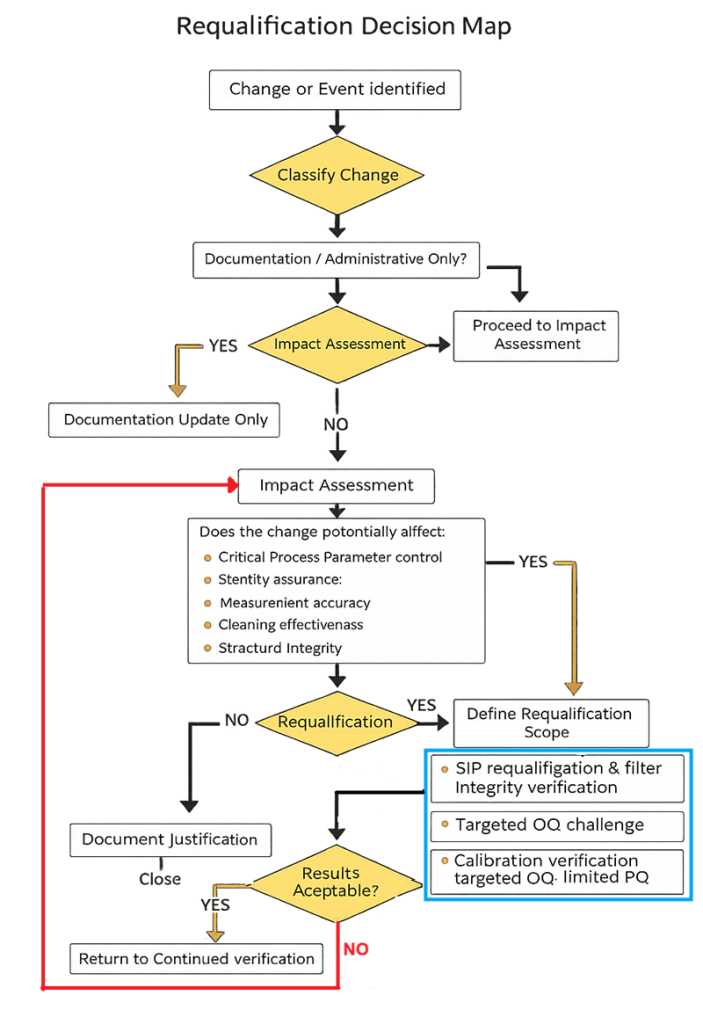
The decision map below defines the structured, risk-based logic used to determine the scope of bioreactor requalification following a change, deviation, or performance trend. It distinguishes documentation-only updates from changes requiring impact assessment, targeted requalification, or corrective investigation, and includes a controlled feedback loop when results are not acceptable.
10. Documentation and Approval
A complete qualification package includes:
- URS and traceability matrix
- Risk assessment
- IQ, OQ, and PQ protocols and reports
- Deviation records
- Summary report stating fitness for intended use
The final report must clearly define:
- Qualified operating ranges
- Approved CIP and SIP parameters
- Maintenance and calibration requirements
- Any operational limitations
11. Conclusion
Bioreactor qualification is the structured demonstration that the system is properly designed, correctly installed, operationally robust, and capable of reproducible performance under defined process conditions. Acceptance criteria must be predefined, scientifically justified, and risk-based. Sterility assurance, measurement reliability, and control stability are central to qualification success. Lifecycle maintenance through calibration, preventive maintenance, change control, and periodic review preserves the validated state and supports continued regulatory compliance.