
Cleanroom Design Principles
Purpose and Positioning
Cleanroom design is not about aesthetics or engineering elegance. It is about risk control. In regulated manufacturing, a cleanroom is a controlled environment engineered to minimize contamination risk to a level appropriate for the product, process, and regulatory classification. Everything else is secondary.
This article establishes foundational cleanroom design principles that regulators implicitly expect, even when they are not explicitly written into code. These principles apply across pharmaceutical, biopharmaceutical, medical device, and compounding environments, with scaling based on risk and product exposure.
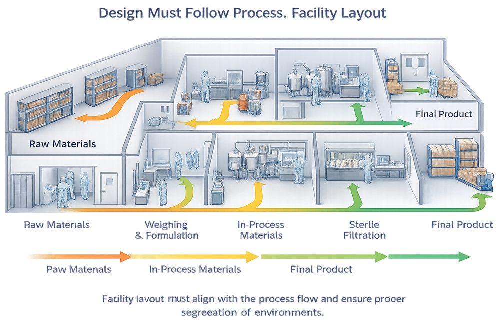
1. Design Must Follow Process
The process defines the cleanroom, not the other way around.
Cleanroom classification, size, layout, and controls must be derived from:
- Product exposure risk
- Open versus closed processing
- Personnel interaction with the product
- Duration of exposure
- Sensitivity of the product to contamination
Designing a cleanroom first and fitting the process into it later is a classic and expensive mistake. Regulators consistently challenge facilities where the cleanroom appears disconnected from how the process actually operates.
2. Contamination Control Strategy as the Backbone
Every cleanroom must be defensible within a documented contamination control strategy, whether formally named or not.
Core contamination vectors addressed by design:
- Personnel
- Materials and components
- Equipment
- Airflow
- Utilities
- Waste
If a contamination pathway exists physically, it exists from a regulatory perspective. Procedural controls alone are not considered robust for primary risk mitigation.
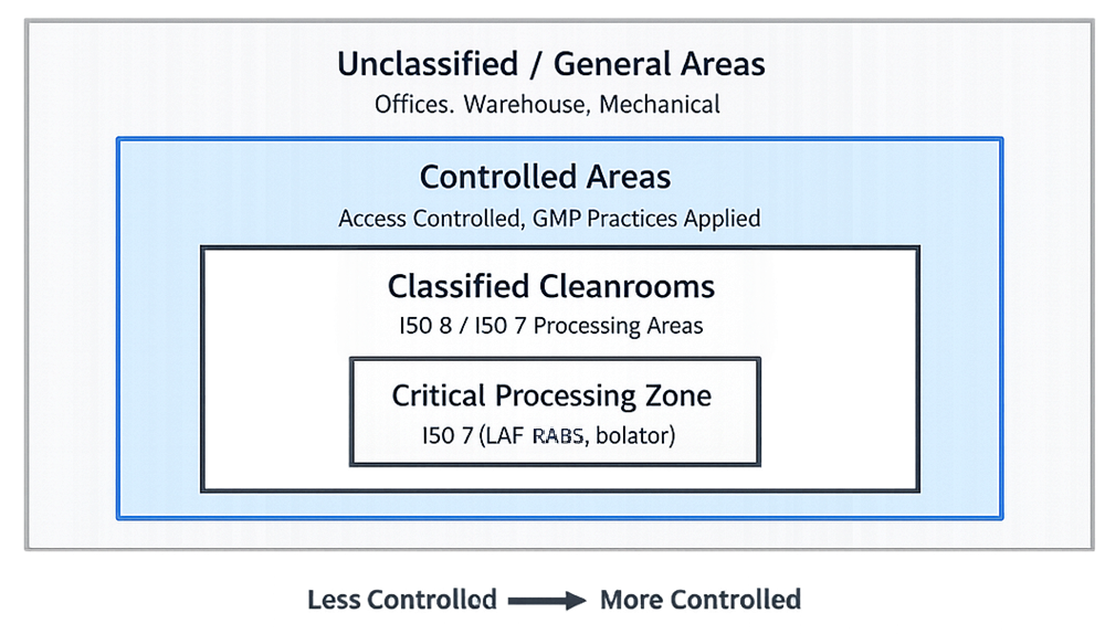
3. Zoning and Cleanliness Hierarchy
Cleanrooms must be designed as part of a graded environment, not as isolated rooms.
Key expectations:
- Clear separation between classified and unclassified areas
- Defined cleanliness progression from entry to critical operations
- Logical pressure cascade aligned with cleanliness levels
Zoning must be obvious to operators and inspectors alike. If it requires explanation, the design is already marginal.
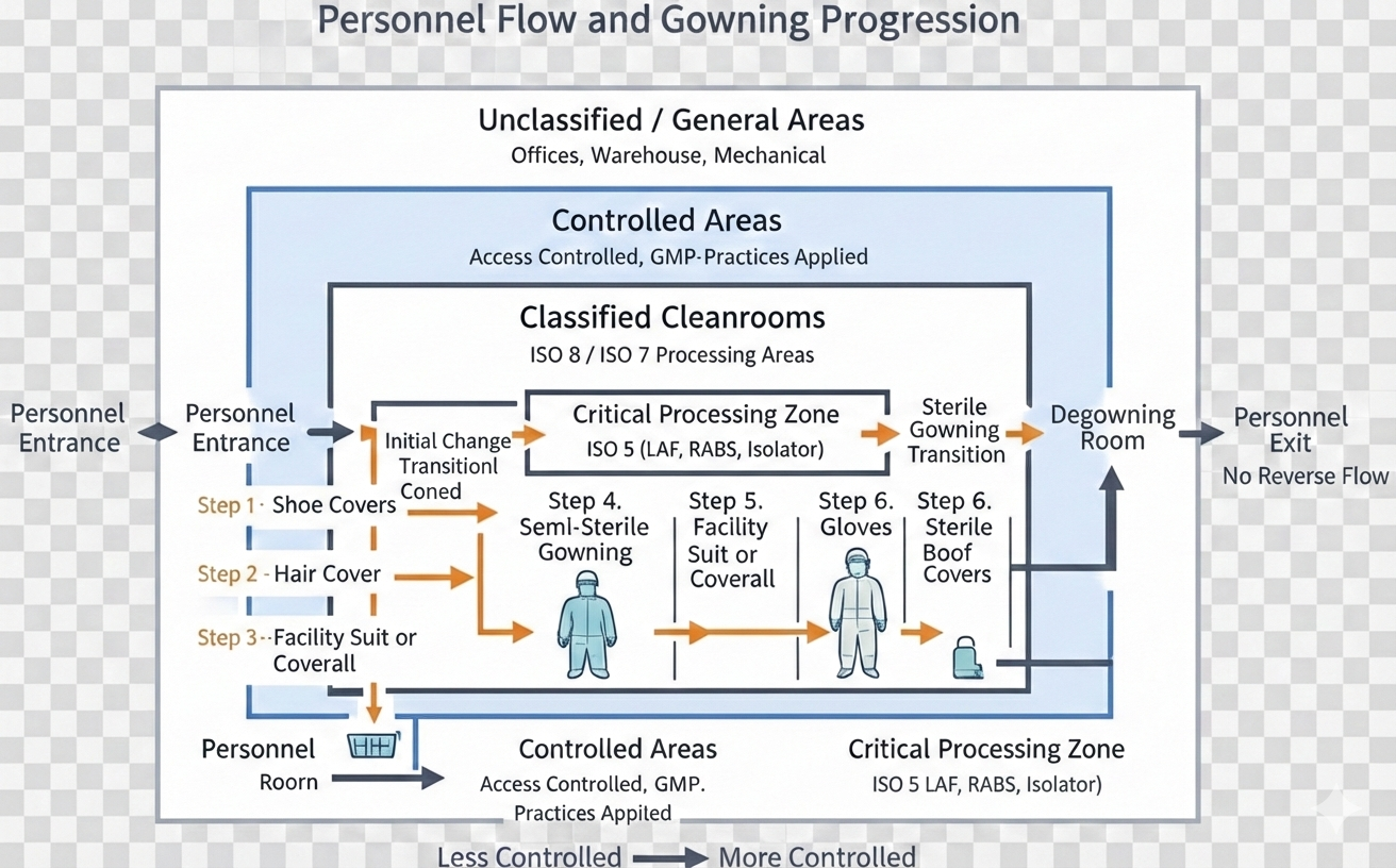
4. Personnel Flow and Gowning Design
Personnel are the dominant contamination source. Cleanroom design must assume this as a baseline truth.
Design principles include:
- Controlled entry points
- Staged gowning and one-directional movement progression
- Physical separation between “dirty” and “clean” sides
- No backtracking
Gowning rooms are not hallways with lockers. They are controlled spaces that directly influence cleanroom performance.
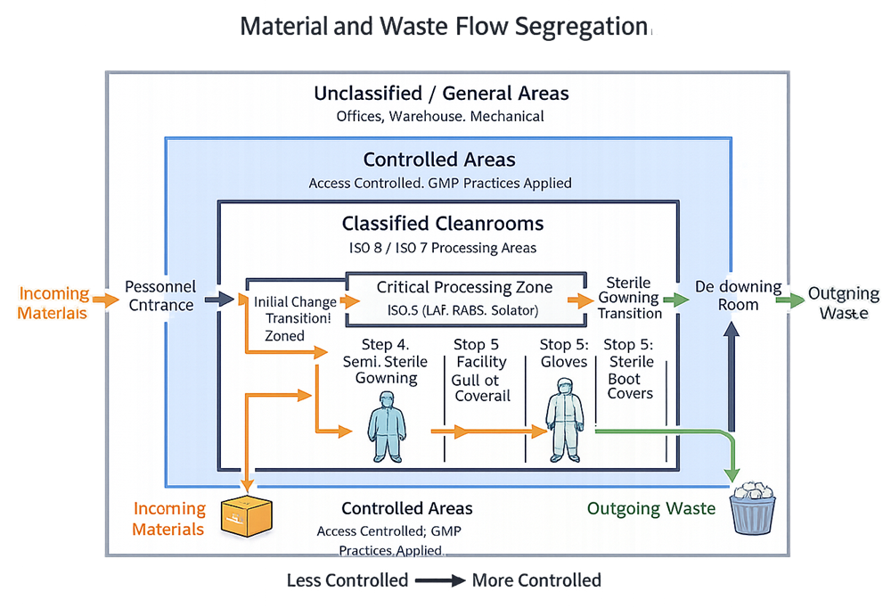
5. Material and Equipment Flow
Material flow must be deliberate, controlled, and segregated from personnel flow where practical.
Best practice design considerations:
- Dedicated material airlocks or pass-throughs
- One-directional flow
- Defined staging areas
- Waste exit routes that do not intersect with incoming materials
Relying on scheduling controls to manage poor layout is a weak justification and rarely survives inspection scrutiny.
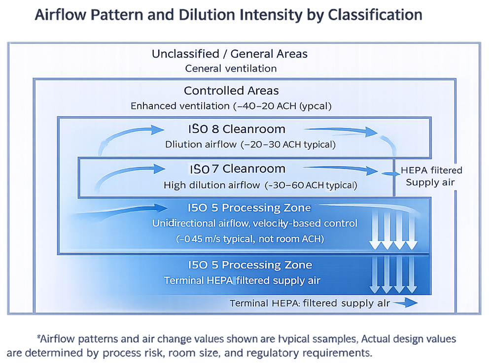
6. Airflow Design and Room Dynamics
Airflow is the primary active contamination control mechanism in a cleanroom.
Design expectations typically include:
- Airflow patterns that sweep contamination away from critical zones
- Adequate air changes per hour
- Recovery times appropriate to classification and risk
- Avoidance of dead zones and turbulence
Airflow must be validated, but it must first be designed correctly. Smoke studies cannot compensate for bad geometry.
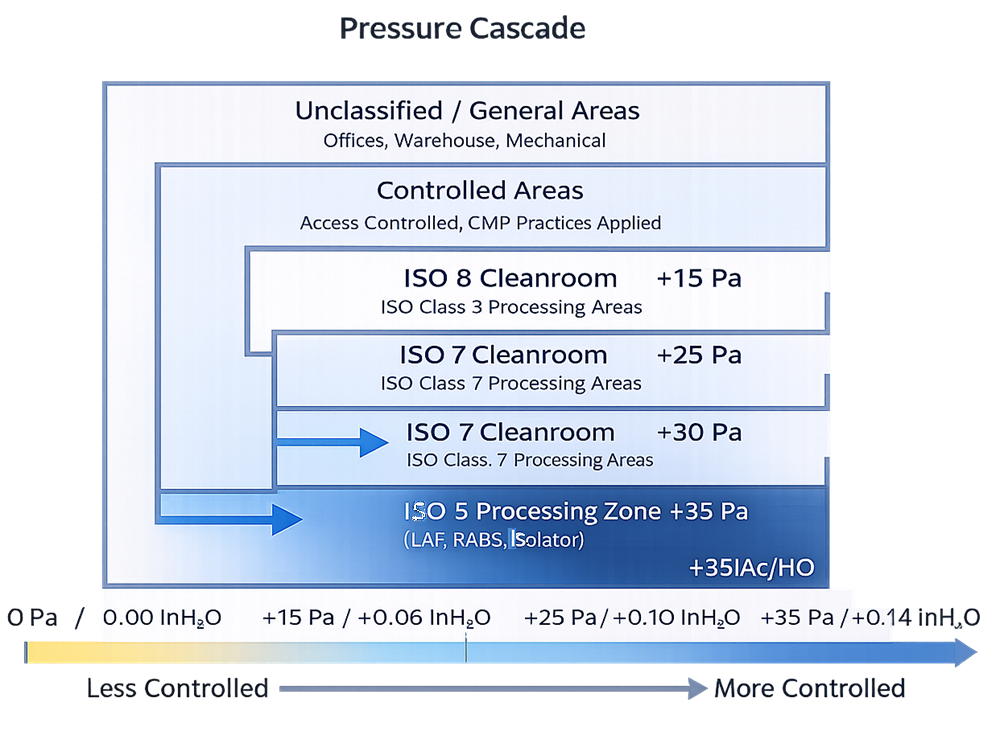
7. Pressure Differentials
Pressure differentials support containment and protection strategies.
Core principles:
- Higher pressure in cleaner areas relative to less clean areas
- Stable and monitorable pressure relationships
- Alarmed conditions where loss of control is critical
If pressure relationships cannot be maintained reliably, the cleanroom classification is theoretical, not real.
8. Materials of Construction
Cleanroom finishes are functional surfaces, not architectural finishes.
Regulatory expectations include:
- Smooth, non-shedding, non-porous materials
- Resistance to disinfectants and cleaning agents
- Minimal seams, ledges, and penetrations
- Flush-mounted fixtures where possible
Anything that traps dirt, moisture, or residue becomes a contamination reservoir.
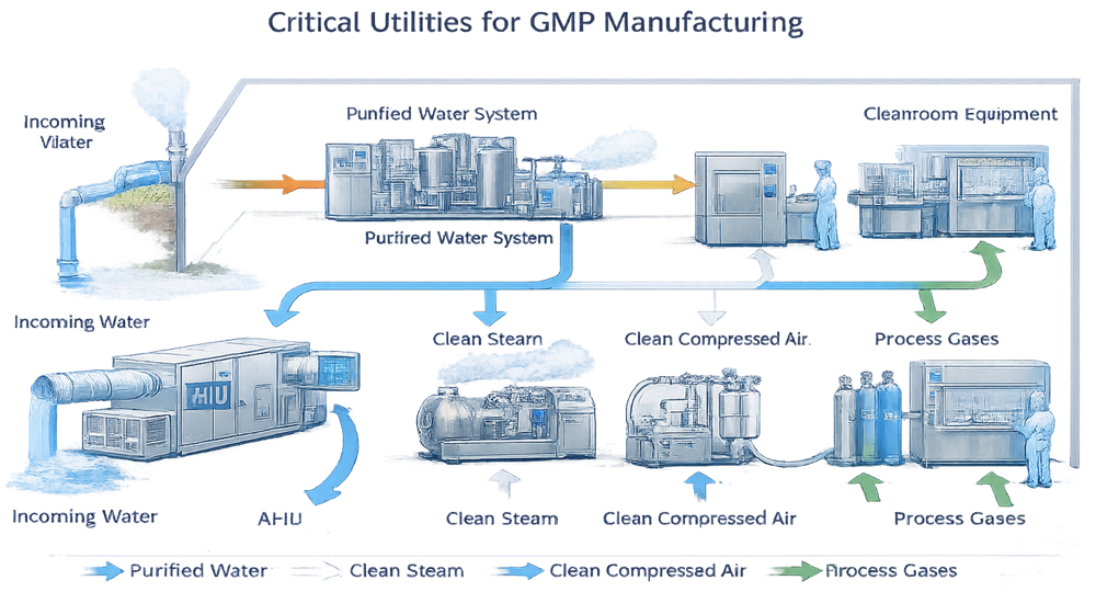
9. Utilities Integration and Boundary Control
Critical utilities are an extension of cleanroom design and must be integrated in a manner that preserves environmental control and contamination prevention. Utilities supporting GMP operations are not independent systems; they interact directly with classified spaces and therefore require deliberate design and control.
Utility routing and connection points must be planned to minimize disruption of cleanroom boundaries and to support effective cleaning, monitoring, and maintenance. Interfaces between utility systems and cleanroom environments should be limited, well-defined, and constructed to maintain surface integrity and cleanability.
Access for installation, inspection, and maintenance should be provided from non-classified areas whenever feasible. Where this is not possible, design controls must ensure that utility interfaces do not compromise room classification, airflow patterns, or pressure control.
From a lifecycle perspective, well-integrated utilities reduce qualification complexity, support reliable operation, and lower the risk of recurring deviations related to maintenance activities or environmental excursions.
10. Design for Qualification and Lifecycle Control
Cleanroom design must support:
- Installation qualification
- Operational qualification
- Environmental monitoring
- Requalification
- Change control
If monitoring probes, HEPA access, or maintenance points are difficult to reach, they will be deferred, rushed, or skipped. Regulators understand this pattern very well.
Common Design Failures Seen by Inspectors
In practice, inspectors repeatedly observe:
- Cleanrooms retrofitted into unsuitable buildings
- Insufficient segregation justified by SOPs
- Overcrowded rooms with excessive equipment
- HVAC systems designed without GMP input
These are not minor findings. They often drive remediation projects that exceed the original build cost.