
Depyrogenation Equipment and Process Design
1. Design Objective
Depyrogenation equipment is designed to achieve controlled thermal destruction of endotoxin on heat-resistant materials. The engineering objective is uniform, reproducible exposure to temperatures capable of achieving defined endotoxin reduction. The design must ensure:
• Uniform temperature distribution
• Controlled airflow dynamics
• Defined exposure time
• Prevention of recontamination during cooling
Unlike sterilization chambers designed for microbial lethality, depyrogenation systems are engineered to deliver sustained high-temperature dry heat exposure.
2. Types of Depyrogenation Equipment
Common equipment configurations include:
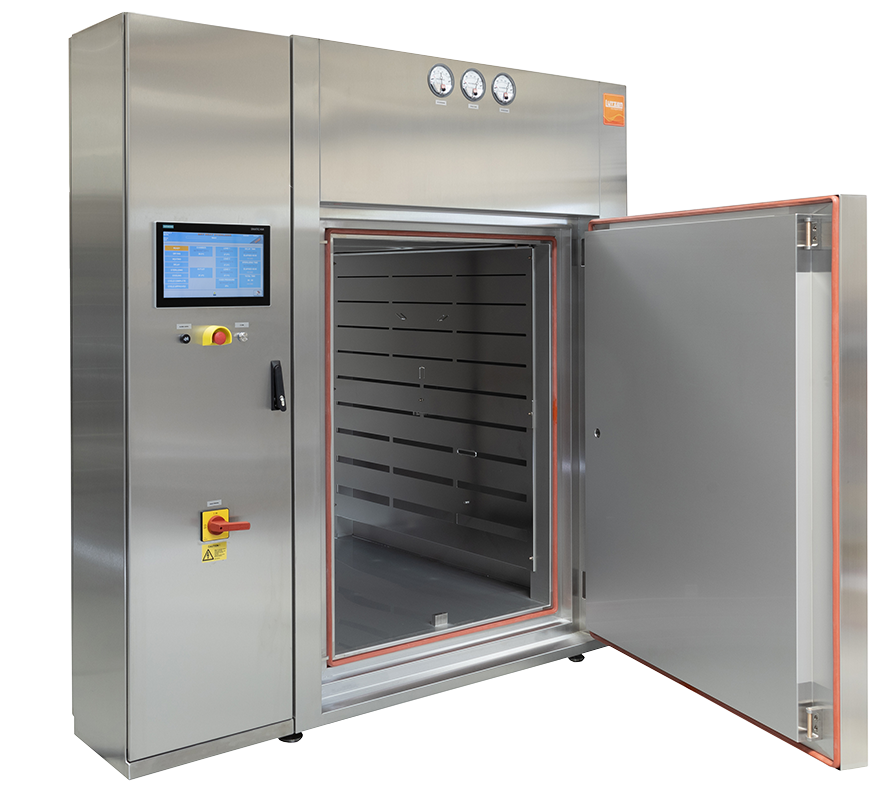
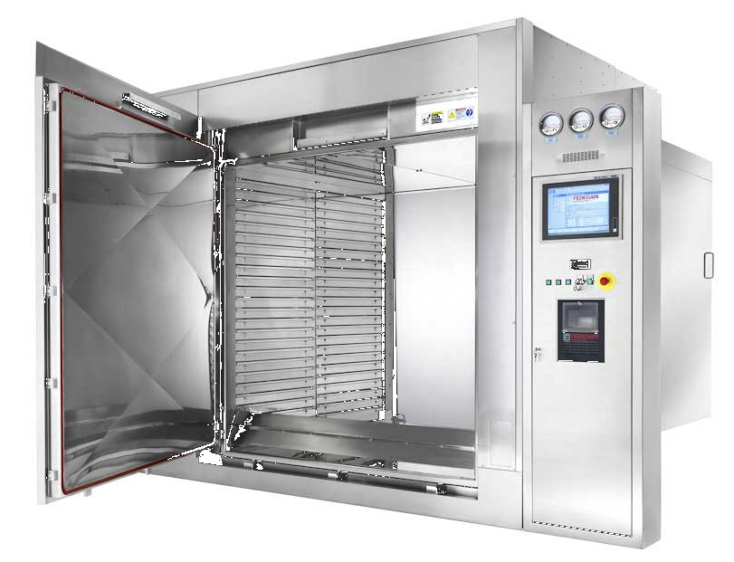
1. Static Dry Heat Ovens
Configuration: Batch chamber with forced-air recirculation.
Thermal Profile
• Typically 200–250 °C setpoint
• Long dwell times
• Heat-up and cool-down phases are significant portions of total cycle time
• Temperature uniformity dependent on airflow distribution and load density
Airflow Characteristics
• Horizontal or vertical recirculation
• Single or dual circulation fans
• HEPA-filtered inlet air
• Risk of localized cold spots if shelving blocks flow
Loading Pattern
• Tray or shelf-based
• Load mass directly affects heat penetration
• Worst case often bottom shelf or high-density stacking
Engineering Challenges
• Uniform temperature mapping across shelves
• Preventing stratification in tall chambers
• Achieving repeatable uniformity under varying load mass
• Seal integrity and door leakage
Typical Use Case
Low to moderate throughput. Flexible for tools and stainless assemblies.
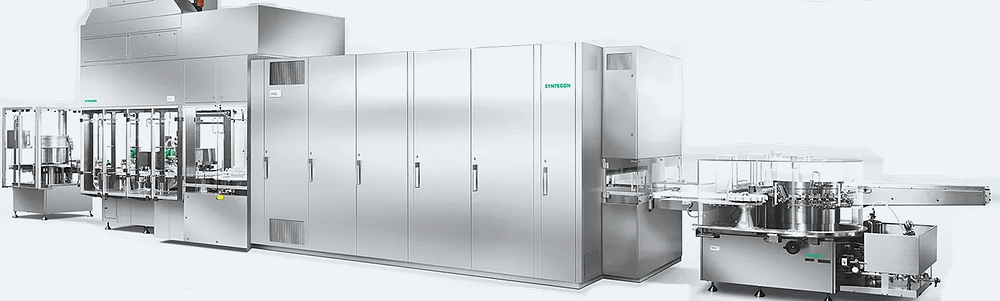
2. Depyrogenation Tunnels
Configuration: Continuous conveyor system with zoned architecture.
Thermal Profile
• Multiple zones: preheat → high-temperature dwell → cooling
• Dwell zone often 250–320 °C
• Residence time controlled by conveyor speed
• Rapid temperature ramp due to forced high-velocity air
Airflow Characteristics
• Vertical unidirectional HEPA-filtered airflow
• Laminar flow over open vials
• High air velocity for rapid heat transfer
• Pressure cascade toward filling area
Loading Pattern
• Individual glass vials transported on mesh belt
• Uniform exposure due to single-layer configuration
• No stacking variability
Engineering Challenges
• Maintaining zone separation
• Airflow balance between heating and cooling
• Contamination control during cooling phase
• Belt speed synchronization with upstream/downstream equipment
Typical Use Case
High-throughput vial processing integrated into aseptic lines.
3. Hybrid Sterilization / Depyrogenation Systems
Configuration: High-temperature chamber engineered for dual capability.
Thermal Profile
• Adjustable setpoints for microbial lethality and endotoxin reduction
• May operate at lower temperature for sterilization and higher for depyrogenation
• Flexible dwell time programming
Airflow Characteristics
• Forced convection similar to static ovens
• May include enhanced airflow for higher heat transfer efficiency
• Not typically zoned like tunnels
Loading Pattern
• Batch configuration
• Mixed material loads possible if compatible
• Greater variability in thermal mass
Engineering Challenges
• Balancing design to satisfy two different performance objectives
• Control system flexibility
• Ensuring consistent validation acceptance criteria for different modes
• Avoiding overexposure damage to materials
Typical Use Case
Facilities requiring flexibility rather than continuous high-volume processing.
Direct Technical Comparison
| Feature | Static Oven | Tunnel | Hybrid System |
|---|---|---|---|
| Operation Mode | Batch | Continuous | Batch |
| Throughput | Low–Moderate | High | Moderate |
| Airflow Pattern | Recirculated convection | Unidirectional laminar | Recirculated convection |
| Load Configuration | Shelves / trays | Single-layer conveyor | Shelves / trays |
| Temperature Uniformity Risk | Shelf-dependent | Zone-dependent | Load-dependent |
| Integration with Filling | No | Yes | No |
| Process Control Driver | Time at temperature | Conveyor speed + zone control | Programmable mode control |
The fundamental engineering distinction:
Static oven → thermal mass management challenge
Tunnel → airflow and zoning control challenge
Hybrid → operational flexibility and control system complexity challenge
3. Thermal Design Considerations
Effective depyrogenation depends on:
• High set-point temperature
• Controlled ramp-up and dwell time
• Stable airflow distribution
• Elimination of cold spots
• Validated load configuration
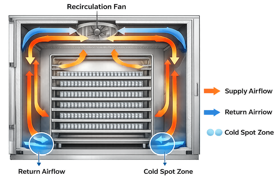
Airflow design is critical. Poor circulation creates temperature gradients that compromise uniform endotoxin reduction. Engineering considerations include:
• HEPA-filtered air supply
• Balanced inlet and exhaust
• Laminar airflow within tunnels
• Controlled conveyor speed in continuous systems
The schematic below illustrates a typical forced-air recirculation pattern within a static dry heat depyrogenation oven. Heated air is driven by an internal circulation fan, distributed across the load, and returned for reheating. Uniform airflow distribution is essential to minimize temperature gradients and prevent localized cold spots that may compromise endotoxin reduction performance.
4. Critical Process Parameters
Depyrogenation processes are defined by tightly controlled parameters, typically including:
• Chamber temperature
• Exposure time
• Air velocity
• Conveyor speed for tunnels
• Load density and configuration
These parameters must be controllable, measurable, and reproducible.
Instrumentation accuracy directly affects process capability.
5. Material Compatibility
Depyrogenation requires high temperatures. Therefore, only heat-stable materials are suitable. Commonly processed materials:
• Borosilicate glass
• Stainless steel
• Certain high-temperature polymers
Material expansion, deformation risk, and particulate generation must be evaluated during design.
6. Contamination Control Design
Design must prevent recontamination after depyrogenation. This includes:
• Controlled cooling zones
• HEPA-filtered airflow
• Positive pressure zones in tunnels
• Defined transfer interfaces to filling operations
For vial tunnels, unidirectional airflow is critical to prevent environmental contamination during cooling.
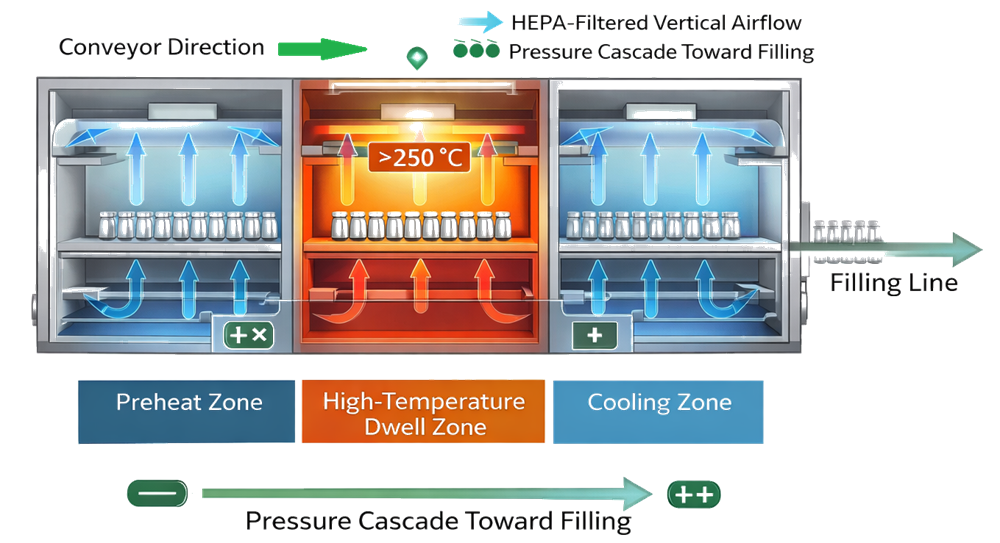
The schematic below illustrates the zoned architecture of a continuous depyrogenation tunnel. Glass containers are transported through sequential preheat, high-temperature dwell, and controlled cooling zones. Each zone is engineered to maintain defined airflow patterns and pressure relationships, ensuring thermal performance while preventing recontamination prior to transfer to the filling line.
7. Design Integration with Manufacturing Flow
Depyrogenation tunnels are often integrated between:
• Vial washer
• Filling line
he interface between depyrogenation equipment and downstream operations must maintain classified environmental conditions consistent with sterile processing requirements under 21 CFR 211, applicable provisions of EU GMP Annex 1 for products distributed in the European Union, and relevant compendial guidance including USP <1116> Microbiological Control and Monitoring of Aseptic Processing Environments.
Equipment design must support cleanroom classification strategy and contamination control.