
Filtration and Ultrafilation System Architecture
1. Introduction
Filtration and ultrafiltration systems are engineered process units used in pharmaceutical and biopharmaceutical manufacturing to achieve defined separation objectives. These objectives may include sterile filtration, bioburden reduction, clarification, concentration, buffer exchange, or viral removal.
In regulated environments, filtration is not simply a membrane element. It is a controlled mechanical and instrumentation assembly designed to operate within validated limits.
System architecture must support:
- Defined intended use
- Product quality protection
- Sterility assurance where required
- Contamination control
- Reproducible performance
- Regulatory compliance
This article addresses the engineered structure of filtration and ultrafiltration systems used in GMP manufacturing.
2. Intended Use and Functional Classification
Architectural requirements are driven by intended use. Filtration systems in pharmaceutical operations generally fall into the following categories:
- Sterile filtration of final drug product
- Bioburden reduction prior to aseptic processing
- Clarification of upstream harvest
- Ultrafiltration for protein concentration
- Diafiltration for buffer exchange
- Viral filtration
- Solvent or buffer preparation filtration
Each application determines:
- Membrane type
- Surface area
- Pressure rating
- Flow regime
- Instrumentation depth
- Qualification strategy
Failure to define intended use results in misalignment between equipment capability and process validation requirements.
3. What Are Ultrafiltration Systems?
Ultrafiltration systems are membrane separation systems designed to retain macromolecules while allowing solvent and low molecular weight species to pass through the membrane.
Unlike sterile filtration, which relies primarily on defined pore size for microbial retention, ultrafiltration membranes are characterized by molecular weight cut-off (MWCO). The membrane selectively retains molecules above a specified molecular size.
Ultrafiltration is commonly used for:
- Concentration of monoclonal antibodies
- Protein purification steps
- Enzyme processing
- Buffer exchange via diafiltration
- Removal of small molecule impurities
In biologics manufacturing, ultrafiltration is often a critical downstream operation. System architecture must therefore protect product integrity, minimize shear exposure, and provide accurate control of pressure and flow.
Ultrafilation systems differ architecturally from simple filter housings because they include separate permeate and retentate flow paths and continuous recirculation capability.
4. Flow Regime Architecture
The fundamental architectural distinction between normal flow filtration and tangential flow filtration lies in the direction of fluid movement relative to the membrane surface. The schematic below illustrates perpendicular flow in dead-end filtration compared with crossflow and recirculation in tangential flow systems. In tangential flow filtration, the portion of fluid that passes through the membrane is referred to as permeate, while the portion retained and recirculated along the membrane surface is referred to as retentate.
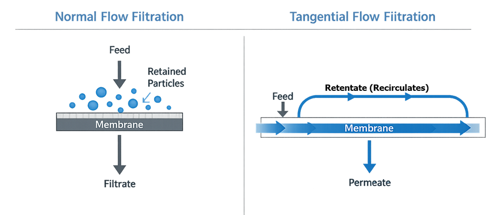
4.1 Normal Flow Filtration
In normal flow (dead-end) filtration, feed is directed perpendicular to the membrane surface. All fluid passes into the membrane, and retained particles accumulate within the filter matrix.
Architecture is typically linear:
Feed → Pump → Filter Housing → Filtrate
Design emphasis includes:
- Differential pressure monitoring
- Throughput limits
- Filter end-point determination
- Overpressure protection
This configuration is typical for sterile filtration and clarification.
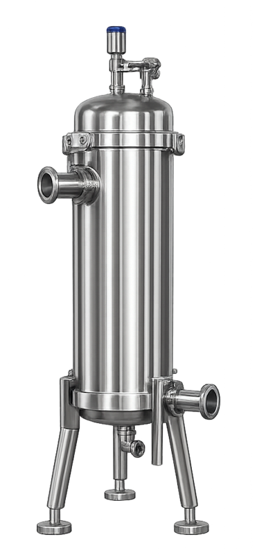
A typical sanitary stainless steel filter housing used for dead-end sterile filtration is shown below. The linear flow path and absence of recirculation distinguish this configuration from tangential flow systems.
4.2 Tangential Flow Filtration (TFF)
Tangential Flow Filtration is the dominant architecture used for ultrafiltration in pharmaceutical manufacturing.
In TFF systems, feed flows parallel to the membrane surface. A controlled portion passes through as permeate, while the remaining stream continues along the membrane surface as retentate and recirculates through the system.
Typical architecture:
Feed Tank → Recirculation Pump → TFF Module → Retentate Return
Permeate → Collection Vessel
A typical pharmaceutical tangential flow filtration system includes a feed vessel, recirculation pump, membrane module, permeate collection line, and continuous retentate return loop. Instrumentation is positioned to monitor transmembrane pressure and process stability. The diagram below illustrates a representative architectural configuration.
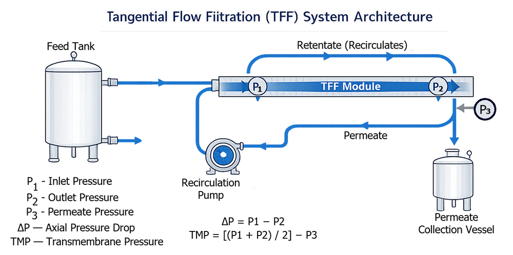
This crossflow design reduces fouling and allows controlled concentration of retained species.
Critical operating parameters include:
- Transmembrane pressure (TMP)
- Crossflow velocity
- Flux rate
- Recirculation stability
- Volume reduction factor
- Temperature control
Because product recirculates continuously, pump selection, loop design, and heat generation must be carefully controlled.
TFF systems are mechanically and operationally more complex than normal flow filtration systems and therefore require expanded instrumentation, control logic, and qualification planning.
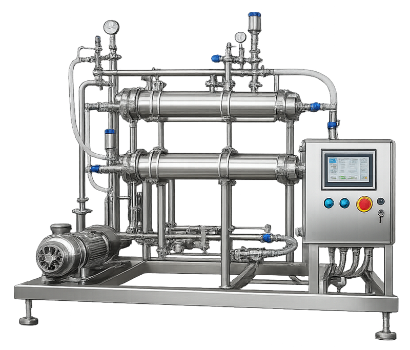
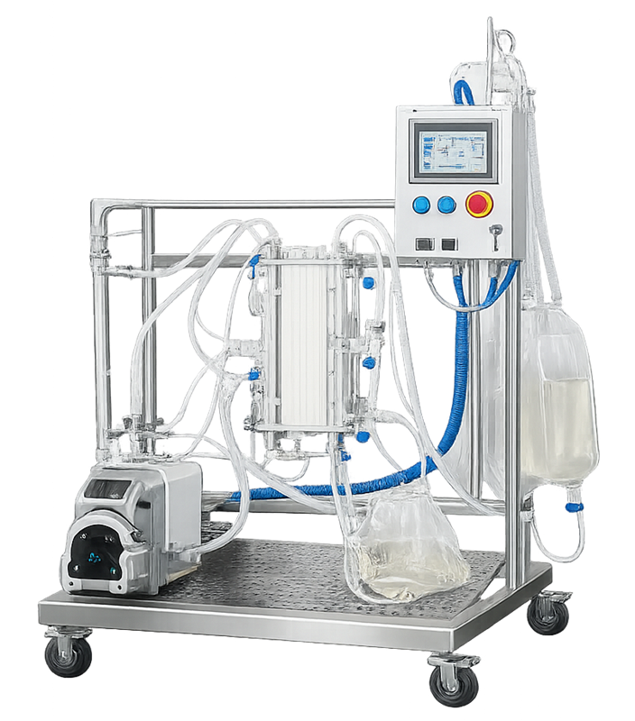
A representative stainless steel tangential flow filtration skid used in biopharmaceutical manufacturing is shown below. Visible recirculation loops, membrane modules, and pressure instrumentation reflect the structural complexity of crossflow systems.”
5. Core Architectural Elements
5.1 Membrane Modules and Housings
Depending on application, systems may include:
- Stainless steel sanitary housings
- Single-use capsule filters
- Hollow fiber cartridges
- Flat sheet cassette modules
Design must ensure:
- Pressure rating compliance
- Complete drainability
- Venting capability
- Minimal stagnant zones
- CIP or SIP compatibility where required
5.2 Pumping Systems
Pump selection affects product integrity and membrane performance.
Common pump types include:
- Peristaltic pumps
- Diaphragm pumps
- Centrifugal pumps
Design considerations include:
- Shear sensitivity
- Pulsation
- Flow stability
- Cleanability
- Heat generation
In TFF systems, recirculation pump stability directly impacts transmembrane pressure control.
5.3 Instrumentation and Monitoring
Validated filtration systems incorporate calibrated instrumentation to monitor critical parameters.
Typical instruments:
- Inlet pressure transmitters
- Outlet pressure transmitters
- Differential pressure measurement
- Flow meters
- Temperature sensors
- Conductivity meters for diafiltration
- Load cells for mass balance
For ultrafiltration systems, continuous monitoring of transmembrane pressure is essential.
Instrumentation placement must support detection of worst-case operating conditions.
5.4 Control System Architecture
Automated filtration skids commonly include PLC-based control systems capable of:
- Valve sequencing
- Pressure control loops
- Alarm management
- Data logging
- Batch integration
Where electronic records are generated, data integrity controls must be implemented consistent with 21 CFR Part 11 requirements when applicable.
Automation depth directly impacts qualification scope.
6. Sanitary Design and Contamination Control Considerations
Filtration systems must be designed to prevent contamination, microbial proliferation, and product accumulation within flow paths.
Design expectations include:
- Orbital welds with inspection records
- Surface finishes compatible with cleanability
- Sanitary or aseptic connections
- Controlled dead-leg ratios
- Complete drainability
- Elimination of stagnant zones
Architecture must support:
- Effective CIP where applicable
- Steam sterilization where required
- Proper venting and condensate removal
- Controlled drying
Material compatibility must be verified for:
- Product chemistry
- Cleaning agents
- Sterilization temperature
- Pressure cycling
Contamination control design is not aesthetic. It is a risk mitigation requirement directly linked to microbial control and endotoxin prevention.
7. Single-Use Versus Stainless Steel Architecture
Stainless Steel Systems
- Fixed piping and manifolds
- CIP/SIP capability
- Broader qualification scope
- Higher capital investment
Single-Use Systems
- Disposable flow paths
- Reduced cleaning validation
- Assembly verification required
- Extractables and leachables evaluation
- Vendor sterilization documentation
A single-use tangential flow filtration configuration is shown below. Disposable tubing, membrane cassettes, and compact frame design shift architectural risk from cleaning validation to assembly integrity and material compatibility.
Architectural risk shifts from cleaning validation to assembly integrity and material compatibility.
8. Utilities and System Boundaries
Filtration systems may interface with:
- Clean steam
- Purified water or WFI
- Compressed air or nitrogen
- CIP systems
- Controlled cleanroom environments
Validation boundaries must clearly define:
- Skid responsibility
- Utility responsibility
- Process validation responsibility
Filtration skids operate within defined architectural and validation boundaries. Supporting utilities and process interfaces must be clearly distinguished from the skid itself to avoid qualification gaps. The diagram below illustrates typical system boundaries and utility connections.
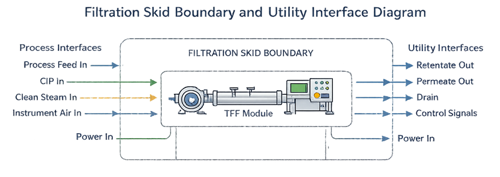
Ambiguous boundary definitions lead to qualification gaps.
9. Architectural Risk Considerations
Common architectural risks include:
- Membrane rupture due to overpressure
- Air entrainment
- Fouling due to inadequate crossflow
- Incomplete sterilization of housings
- Dead-leg contamination
- Alarm failure
- Control logic instability
Architecture must allow both prevention and detection of these failure modes.
10. Relationship to Qualification and Process Validation
System architecture determines:
- Qualification depth
- Integrity testing strategy
- Alarm limits
- Calibration scope
- Preventive maintenance requirements
Equipment qualification demonstrates that the system operates as designed. Process validation demonstrates that the process achieves its intended performance under defined conditions.
11. Conclusion
Filtration and ultrafilation systems are engineered process units whose architecture must align with defined intended use, product risk profile, and regulatory expectations.
System architecture integrates:
- Sanitary mechanical design
- Appropriate membrane configuration and flow regime
- Controlled pressure and flow management
- Robust instrumentation and monitoring
- Defined automation and alarm logic
- Utility compatibility
- Clear qualification and validation boundaries
Architectural design precedes qualification. Equipment qualification confirms the system operates as designed. Process validation confirms the process performs as intended.
A properly designed filtration system supports predictable performance, simplifies qualification, and reduces operational risk. Inadequate architectural design increases validation burden, contamination risk, and lifecycle instability.