
GMP Filtration Skid Design and Qualification
A GMP filtration skid is a controlled process system that integrates mechanical design, instrumentation, and automated control to ensure consistent filtration performance and protection of product quality. Design and qualification must address both the physical flow path and the automation functions that govern critical process parameters. The skid is validated as a single, defined system with clear boundaries, documented requirements, and lifecycle control.
The objective is to demonstrate that the skid is properly designed, installed, operated, and maintained in a state of control suitable for regulated manufacturing environments.
1. System Definition and Intended Use
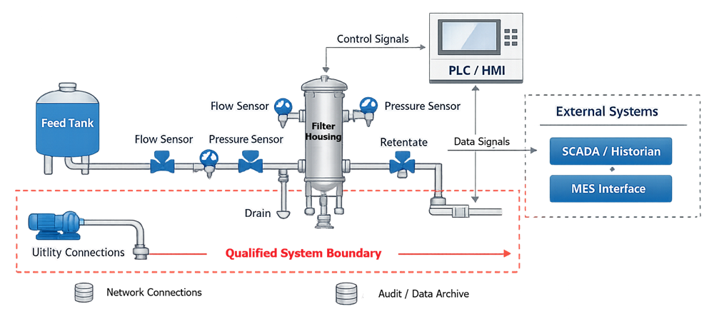
The system definition establishes the qualified boundary and intended function. A typical GMP filtration skid may include:
• Feed and recirculation pumps
• Filter housings and membrane assemblies
• Automated process valves
• Pressure, flow, and temperature instrumentation
• Control panel with PLC
• Human-machine interface
• Data acquisition modules
• Utility connections
The intended use must define whether the skid supports sterile filtration, depth filtration, ultrafiltration, or tangential flow filtration. It must also specify whether the system operates in batch, semi-continuous, or continuous mode.
All direct-impact components must be identified. This includes process-contact materials, instrumentation controlling critical parameters, and automation logic governing routing, interlocks, and alarms.
The diagram below defines the functional architecture of the GMP filtration skid and establishes the qualified system boundary. It illustrates the relationship between major mechanical components, process instrumentation, automation hardware, and external interfaces. The intent is to clearly distinguish process flow path elements from control and data layers, and to identify where direct-impact components reside within the overall system structure.
2. Design Principles
GMP-compliant filtration skid design must integrate hygienic engineering, formal risk management, and a defined process control strategy. The skid is not simply a piping assembly; it is a controlled processing unit that must maintain product protection, pressure stability, and repeatable performance under defined operating limits.
Design decisions must be traceable to process risk. Each component, instrument, and control function should support contamination prevention, parameter control, and operator safety.
2.1 Mechanical Design
Mechanical design considerations include:
• Materials of construction compatibility
Materials must be chemically compatible with process fluids, cleaning agents, and sanitization conditions. Extractables, leachables, and corrosion resistance must be evaluated where applicable. Elastomers, gaskets, and seals must be suitable for pressure and temperature ranges.
• Surface finish and cleanability
Process-contact surfaces must support cleaning and, where required, sterilization. Surface roughness should be controlled to prevent microbial retention. Crevices, threaded connections in product-contact zones, and trapped volumes must be avoided.
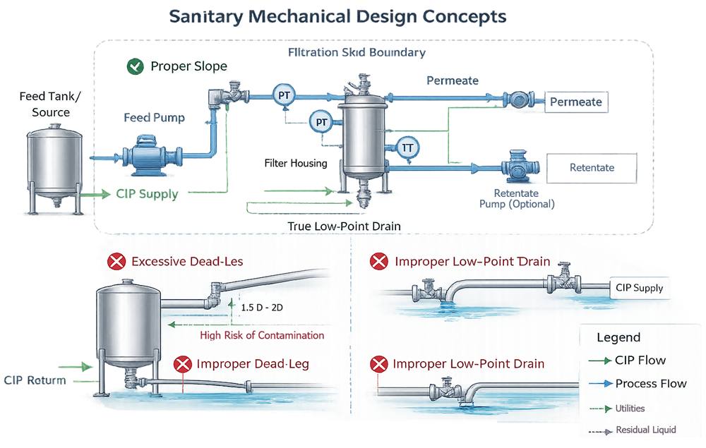
• Drainability and elimination of dead legs
Piping geometry must support complete drainage. Dead legs exceeding acceptable length-to-diameter ratios increase microbial risk and compromise cleaning validation. Drain ports must be positioned at true low points.
• Proper slope and low-point drainage
Horizontal runs must be sloped to ensure fluid evacuation. Low-point drains must be accessible and clearly identified. Drain design must prevent residual pooling after CIP or product transfer.
The illustration below demonstrates sanitary mechanical design principles applicable to GMP filtration skids. It highlights proper piping slope, controlled dead-leg geometry, verified low-point drainage, and defined CIP return flow paths. The diagram emphasizes how piping configuration and component layout directly affect cleanability, contamination control, and validation robustness.
• Pressure rating adequacy
All components, including housings, valves, and fittings, must be rated for maximum allowable operating pressure with appropriate safety margin. Transient conditions such as pump startup or valve closure must be considered.
• Filter housing integrity
Filter housings must maintain structural integrity under maximum differential pressure. Design must support integrity testing where applicable and prevent bypass around the filter element.
Instrumentation must be positioned to provide accurate representation of critical process parameters. Transmembrane pressure measurement requires correct placement of feed, retentate, and permeate sensors to prevent distorted readings. Flow sensors must be located in stable flow regions to avoid turbulence-induced inaccuracies. Improper placement can produce misleading control responses and compromise process validation.
2.2 Automation Design
Automation design must formally define the control philosophy.
The following diagram illustrates the high-level automation control strategy governing the filtration skid. It identifies primary control loops, alarm blocks, interlock logic, valve sequencing structure, and defined fail-safe outputs. The diagram clarifies how automation maintains critical process parameters within validated limits and prevents incompatible routing or over-pressurization conditions.
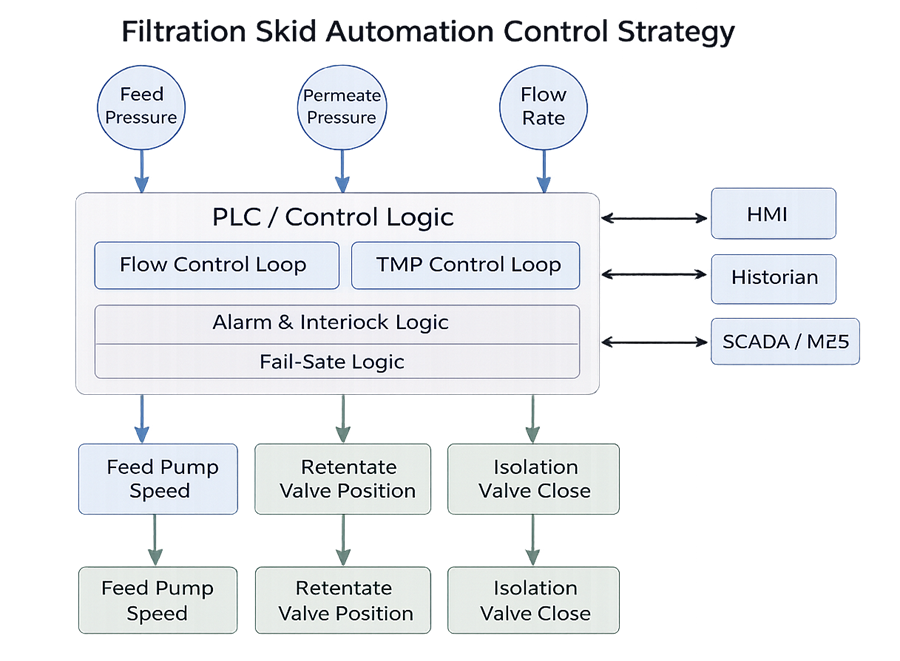
• Control loop configuration
Primary control variables must be identified. Loop architecture may include PID control, cascade control, or ratio control depending on process requirements. Loop tuning strategy must support stability across the operating range.
• Alarm thresholds
Alarm limits must be scientifically justified and aligned with validated operating ranges. Distinction between alert and action levels must be defined.
• Interlock logic
Interlocks must prevent unsafe or incompatible conditions such as dead-head pumping, closed-valve pressurization, or cross-contamination routing. Interlocks must default to a safe state under fault conditions.
• Valve sequencing
Automated valve actuation must follow defined sequences to prevent hydraulic shock, cross-flow contamination, or pressure imbalance. Sequencing logic must be deterministic and documented.
• Fail-safe states
Loss of power, air supply, or controller fault must drive valves and pumps to predetermined safe conditions. Fail-safe configuration must be risk-based and justified.
• Manual override governance
Manual mode must be controlled. Override capability must be restricted, traceable, and governed by procedural controls to prevent unintended operation outside validated parameters.
The control strategy must ensure that incompatible routing is impossible without deliberate, authorized intervention. It must prevent over-pressurization through mechanical safeguards and automation interlocks. Operation outside validated ranges must trigger alarm and protective response.
Design must therefore anticipate normal operation, abnormal conditions, and failure modes. A filtration skid that is mechanically robust but poorly controlled remains a compliance risk. Design integrity and control integrity are inseparable in GMP filtration systems.
3. User Requirements Specification
The User Requirements Specification establishes measurable expectations for performance and compliance. The URS must define:
• Intended filtration application
• Operating pressure and flow ranges
• Transmembrane pressure limits
• Alarm setpoints
• Interlock requirements
• Data recording expectations
• User access control requirements
• Regulatory compliance considerations
Automation requirements must be explicit and traceable. Functional descriptions must define how the skid responds under normal, abnormal, and fault conditions.
4. Design Qualification
Design Qualification confirms that the mechanical and automation design satisfy the URS.
Mechanical DQ verifies:
• Materials of construction
• Hygienic design compliance
• Instrument location adequacy
• Valve routing logic
• Pressure rating and safety margins
Automation DQ verifies:
• Alignment of functional specification with URS
• Complete and accurate I/O mapping
• Defined alarm and interlock logic
• Fail-safe configuration
• Data integrity architecture
All approved P&IDs, electrical drawings, control narratives, and specifications must reflect the final design configuration.
5. Installation Qualification
Installation Qualification confirms that the skid is installed according to approved documentation.
Mechanical IQ includes:
• Component identification verification
• P&ID reconciliation
• Instrument tag verification
• Utility connection verification
• Panel layout confirmation
Automation IQ includes:
• PLC hardware verification
• Firmware documentation
• I/O module verification
• Wiring inspection
• Network configuration documentation
• Backup and restore verification
As-built documentation must match approved drawings and specifications.
6. Operational Qualification
Operational Qualification verifies functional performance across defined operating ranges. Mechanical OQ includes:
• Pump performance verification
• Pressure boundary integrity testing
• Valve actuation verification
• Instrument calibration confirmation
• Flow verification testing
Automation OQ includes:
• I/O point verification
• Control loop challenge testing
• Alarm setpoint verification
• Interlock challenge testing
• Fail-safe state verification
• Power failure and restart simulation
• User access testing
• Audit trail verification
The system must demonstrate protective response to parameter excursions and routing errors.
7. Performance Qualification
Performance Qualification confirms reproducibility during routine operation. PQ activities may include:
• Execution of defined filtration runs
• Monitoring of transmembrane pressure stability
• Confirmation of flow control consistency
• Alarm performance monitoring
• Verification of data recording integrity
Worst-case operating conditions must be defined and justified.
8. Data Integrity and Automation Governance
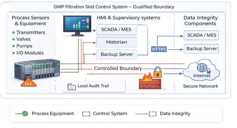
When a filtration skid generates electronic data used for batch release, quality review, deviation investigation, or process trending, the automation platform becomes a regulated system. Data integrity controls are not optional features; they are validated system requirements.
Data governance must be designed, not retrofitted. The architecture must ensure that data are attributable, legible, contemporaneous, original, and accurate throughout the system lifecycle.
The diagram below defines the electronic data boundary associated with the filtration skid automation system. It identifies where GMP-relevant data are generated, stored, transmitted, and archived. The illustration clarifies responsibility for audit trails, time synchronization, backup control, and validated interfaces with external systems such as historians or manufacturing execution platforms.
8.1 User Access and Identity Management
The automation platform must enforce unique user identification. Shared accounts are unacceptable in GMP environments where electronic data support quality decisions.
The system must provide:
• Individual user IDs
• Strong authentication mechanisms
• Defined password complexity rules
• Account lockout after repeated failed attempts
• Session timeout controls
Role-based permissions must restrict access according to job function. Operators, supervisors, engineers, and administrators must have clearly segregated privileges. Administrative access must be limited and formally authorized.
Any change to user roles must be governed by documented procedures and subject to periodic review.
8.2 Audit Trail Controls
Audit trails must automatically record all GMP-relevant actions without the possibility of user disablement. The audit trail must capture:
• User identification
• Date and time stamp
• Previous value
• New value
• Reason for change where required
Audit trails must apply to:
• Setpoint changes
• Alarm threshold modifications
• Control logic adjustments
• Batch parameter changes
• User account modifications
Audit trail records must be secure, non-editable, and retrievable for review. Periodic audit trail review should be defined in SOPs and documented.
8.3 Time Synchronization
All electronic records must rely on accurate and consistent system time. The automation system must:
• Synchronize to a controlled time source
• Maintain consistent timestamps across PLC, HMI, and historian
• Protect time configuration from unauthorized modification
Time discrepancies between components can compromise record traceability and must be eliminated through controlled configuration.
8.4 Data Storage and Protection
Electronic data must be protected from loss, alteration, or unauthorized access. The system must ensure:
• Secure data storage locations
• Access control to raw data files
• Protection against overwriting
• Virus and malware safeguards where applicable
• Controlled configuration management
If local storage is used on the skid HMI or PLC, safeguards must prevent unauthorized extraction or deletion of data.
8.5 Backup and Disaster Recovery
Backup strategy must be documented, validated, and periodically verified. The backup plan must define:
• Frequency of automated backups
• Scope of backup including configuration files, logic, and data
• Secure storage location
• Retention period
• Restoration testing frequency
Backup restoration must be periodically tested to confirm recoverability. A backup that has never been restored is not verified.
8.6 Electronic Records and Regulatory Compliance
If electronic records replace paper batch documentation or support release decisions, regulatory requirements for electronic records apply. The system must demonstrate:
• Controlled record generation
• Protection against record deletion
• Record retention in accordance with company policy
• Controlled export of data
• Verification that exported data match original records
If electronic signatures are implemented, signature meaning, linking, and authentication controls must be validated.
8.7 Interface and Integration Validation
Integration with external systems such as SCADA, historians, MES, or LIMS introduces additional risk at the data transfer boundary. Interface validation must confirm:
• Data completeness during transfer
• Data accuracy and format integrity
• Alarm and event consistency
• No unintended data truncation
• Secure communication protocols
Where data are transmitted over networks, cybersecurity risk assessment must be performed. Network segmentation, firewall configuration, and access control policies must be documented.
8.8 Periodic Review and Ongoing Governance
Data integrity is maintained through continuous oversight. Periodic review should include:
• User access reconciliation
• Audit trail review
• Alarm change history review
• Backup restoration testing
• Firmware and configuration verification
Automation governance is not limited to initial qualification. It must remain under controlled lifecycle management to ensure that filtration process data remain reliable, traceable, and defensible during regulatory inspection.
9. Change Control and Lifecycle Oversight
All modifications to mechanical components, instrumentation, or control logic must be governed by formal change control.
Requalification may be required following:
• Software revision
• PLC hardware replacement
• Instrument replacement affecting critical parameters
• Filter type change
• Setpoint modification
• Control strategy changes
Periodic review should assess alarm trends, loop stability, deviation history, and system configuration integrity.
A GMP filtration skid must remain in a validated state throughout its operational life. Design and qualification must be structured to ensure continued fitness for intended use under controlled conditions.