
HVAC System Architecture and Components
From a GMP standpoint, HVAC is not a comfort system—it is a product-quality control system. Its architecture must be deliberate, conservative, and proven in regulated environments. Novelty adds risk; standardization adds control. Below is a practical, regulator-tested breakdown.
1. System Architecture Overview
A GMP HVAC system is typically centralized and hierarchical, designed to deliver consistent, controlled air to classified and non-classified areas while maintaining pressure cascades and environmental limits.
Typical architecture
- Central or semi-central Air Handling Units (AHUs)
- Zoned distribution to rooms or suites with similar cleanliness and risk profiles
- Terminal control at the room level where product exposure exists
- Central monitoring and alarm management via BMS or EMS
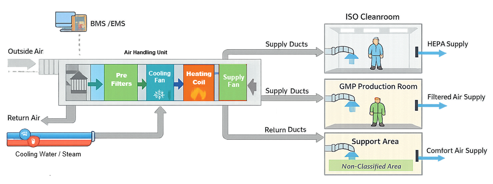
This structure supports segregation, change control, and qualification discipline. Decentralized or comfort-style layouts rarely age well under inspection. The diagram below illustrates a typical GMP HVAC system architecture and its primary functional components.
Typical GMP HVAC System Architecture
2. Air Handling Units (AHUs)
The AHU is the backbone of the system and must be designed for stability, accessibility, and cleanability. Core AHU components
- Fresh air intake with weather louvers and pre-filtration
- Mixing box for return and outside air
- Pre-filters and fine filters
- Heating and cooling coils
- Humidification or dehumidification stages where required
- Supply and return fans with VFD control
For GMP use, AHUs should be dedicated by function or cleanliness class where feasible. Shared AHUs across dissimilar operations are a common audit vulnerability.
3. Filtration Strategy
Filtration is layered and intentional. Each stage protects the next. Typical filtration train
- Pre-filters to protect coils and downstream filters
- Intermediate filters for particulate load reduction
- HEPA filters at terminal locations or within the AHU for classified spaces
Terminal HEPA filters remain the gold standard in aseptic and controlled environments because they:
- Localize risk
- Simplify integrity testing
- Reduce cross-room dependency
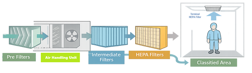
The diagram below illustrates the staged filtration approach typically used in GMP HVAC systems, from air intake through terminal HEPA filtration. The diagram below illustrates the staged filtration approach typically used in GMP HVAC systems, from air intake through terminal HEPA filtration.
Stage Filtration Diagram
4. Air Distribution and Return
Air distribution defines how effectively the system controls contamination. Key elements
- Supply ductwork designed for balanced airflow
- Ceiling diffusers or laminar flow devices in critical areas
- Low-wall or ceiling returns depending on room classification
- Minimal dead legs and accessible duct routing
Uniform airflow matters more than high airflow. Excess air changes are not a substitute for good design.
5. Pressure Cascades and Zoning
Pressure control is fundamental to contamination control. Standard practice
- Positive pressure for clean areas relative to adjacent spaces
- Negative pressure where containment is required
- Clearly defined pressure zones aligned with process flow
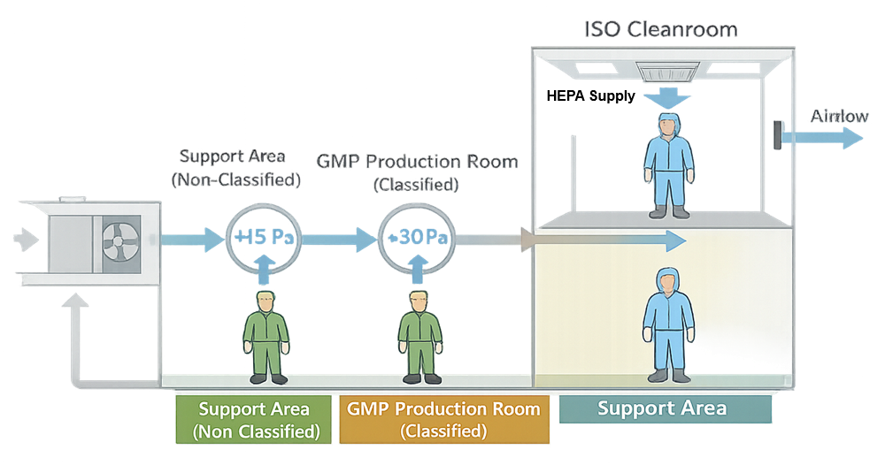
Pressure differentials should be modest, stable, and continuously monitored. Over-pressurization causes more problems than it solves. Pressure cascades are used in GMP facilities to control airflow direction between adjacent areas of differing classification.
Typical GMP Pressure Cascade
6. Controls, Sensors, and Automation
Manual control is obsolete in regulated facilities. Common control elements
- Temperature sensors
- Relative humidity sensors
- Differential pressure transmitters
- Airflow or fan status indicators
These feed into the Building Management System (BMS) and, where product quality is directly impacted, an Environmental Monitoring System (EMS). Alarm rationalization is critical—too many alarms undermine compliance.
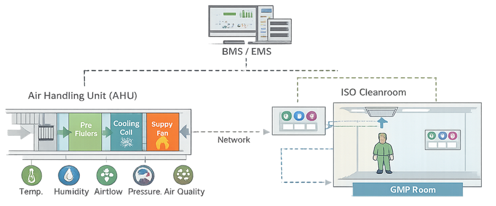
HVAC operating parameters are monitored and controlled through integrated building and environmental monitoring systems.
HVAC Controls and Monitoring Integration
7. Supporting Utilities and Interfaces
HVAC does not operate in isolation. Typical interfaces
- Chilled water and hot water systems
- Steam or clean steam for humidification
- Electrical power with backup where required
- Fire and life-safety systems
Each interface must be documented, assessed for risk, and addressed during qualification.
Design Principles and Summary
The HVAC architecture and associated components establish the means by which environmental conditions are controlled, monitored, and demonstrated within GMP facilities. System design is expected to support consistent airflow, effective filtration, stable pressure relationships, and reliable temperature and humidity control appropriate to the intended use of each space.
From both a design and operational perspective, a compliant HVAC system incorporates:
- Established system layouts commonly used in regulated manufacturing environments
- Zoning and segregation aligned with process flow and contamination risk
- Terminal HEPA filtration in areas where product or critical operations are exposed
- Clearly defined and maintainable pressure differentials between adjacent spaces
- Automated control and monitoring through building and environmental management systems
These elements collectively support qualification, routine operation, deviation investigation, and requalification activities by providing a stable, understandable, and verifiable state of environmental control throughout the system lifecycle.