
Isolator Systems for Aseptic Processing
1. Purpose and Scope
Isolator systems are sealed barrier enclosures designed to provide a controlled internal environment for aseptic processing with minimal reliance on surrounding cleanroom conditions. Unlike open barrier technologies, isolators establish a physically separated processing chamber that incorporates engineered airflow control, pressure regulation, and validated bio-decontamination capability.
The purpose of this article is to define the engineering principles, contamination control logic, qualification strategy, and lifecycle management requirements associated with isolator-based aseptic processing. The discussion addresses airflow architecture, pressure regimes, decontamination systems, intervention control, transfer interfaces, and regulatory expectations.
The focus is on pharmaceutical sterile manufacturing applications where isolators are used for filling, compounding, or other operations involving exposed sterile product.
2. Fundamental Design Principles
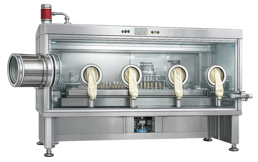
An isolator is a fully enclosed system that physically separates the aseptic processing environment from the surrounding cleanroom. The enclosure is constructed from rigid panels with sealed joints and integrated glove ports that permit operator interaction without breaching the barrier. Access doors are gasketed and interlocked to preserve enclosure integrity.
A typical aseptic isolator consists of a sealed stainless steel enclosure with glove ports, integrated transfer systems, and internal HEPA-filtered airflow designed to operate independently of the surrounding cleanroom.
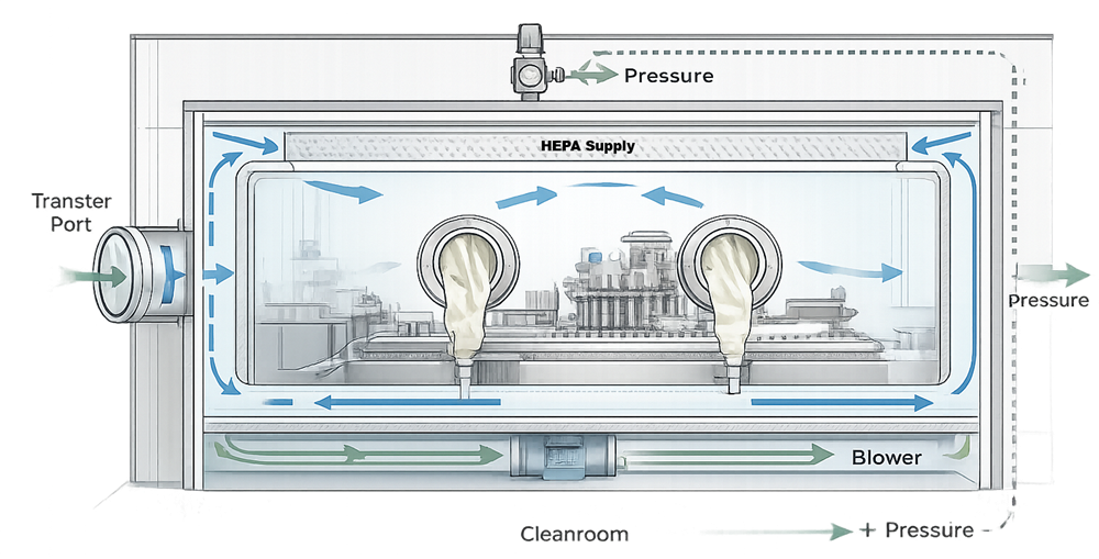
Inside the isolator, HEPA-filtered unidirectional airflow is delivered over critical processing zones to maintain ISO 5 conditions. Air is recirculated within the enclosure or exhausted through controlled filtration depending on process design. Unlike RABS, isolators are engineered to operate independently of room air patterns, and their internal performance does not depend on ceiling filter alignment in the surrounding cleanroom.
A defining feature of isolators is their capability for automated bio-decontamination, typically using vaporized hydrogen peroxide. This enables the enclosure interior to be rendered microbiologically clean prior to production, reducing reliance on manual disinfection and operator technique alone.
The design objective is not only first air protection but also controlled environmental isolation, validated decontamination, and reduced contamination risk from human intervention.
A typical isolator architecture illustrates the sealed enclosure, internal airflow system, and pressure control independent of the surrounding cleanroom.
3. Isolator vs RABS – Engineering Distinction
Although both isolators and RABS are barrier technologies, their engineering logic differs substantially.
A RABS functions as a restricted barrier within a cleanroom and remains dependent on background HVAC stability. It is not hermetically sealed and does not support automated bio-decontamination of the full enclosure. Operator access, even when restricted, remains more directly connected to room airflow dynamics.
An isolator, by contrast, is a sealed enclosure with defined leak integrity and an independent internal airflow system. It incorporates validated bio-decontamination cycles, typically using VHP, and can maintain ISO 5 conditions within the chamber regardless of minor fluctuations in surrounding room airflow. Pressure differentials are established between the isolator interior and the cleanroom to control ingress or egress of air.
The contamination control strategy for isolators relies on:
- Physical separation
- Validated decontamination
- Controlled pressure regime
- Limited and engineered transfer systems
This architecture reduces operator-related contamination risk and enables more controlled aseptic processing environments.
4. Airflow and Pressure Control
Isolators utilize internally mounted HEPA filters to generate unidirectional airflow across the defined critical processing zone. The airflow system must maintain uniform velocity and directional stability over exposed sterile components, with engineered recirculation paths and return plenums designed to minimize turbulence, stagnation, and short-circuiting.
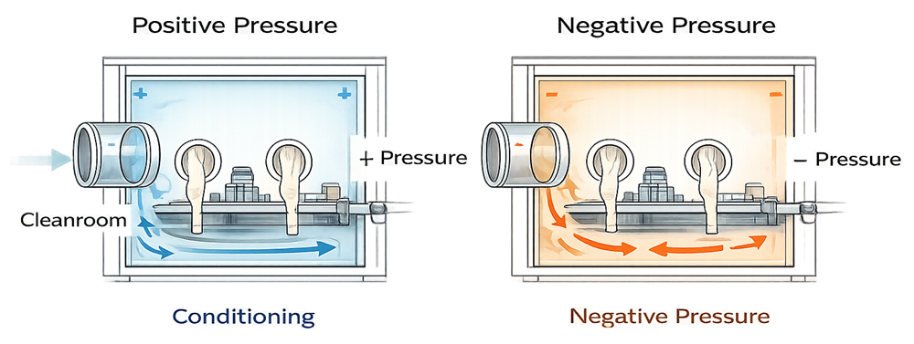
Pressure regime is a defining design parameter. In product-protection applications, isolators operate under positive pressure relative to the surrounding cleanroom so that any leakage path results in outward airflow, protecting sterile product from room ingress. In containment applications involving potent compounds or hazardous materials, isolators operate under negative pressure relative to the room, ensuring that any leakage results in inward airflow and containment of hazardous particulates or vapors within the enclosure.
Negative pressure isolators require controlled exhaust management, often through dedicated ducting and monitored pressure cascades, to maintain stable containment. Pressure setpoints must be justified, continuously monitored, and alarmed. Loss of pressure control in either regime directly compromises the intended protection function—either sterility assurance in positive systems or operator/environmental protection in negative systems.
Because the enclosure is sealed, internal airflow stability depends primarily on blower performance, HEPA filter loading, control system response, and seal integrity rather than on ceiling diffuser layout. However, external HVAC performance still influences the surrounding pressure cascade and must be incorporated into system design and qualification.
Airflow visualization studies are required to demonstrate directional stability under static and dynamic conditions, particularly around glove ports, transfer systems, and internal equipment that may disrupt first air.
5. Bio-Decontamination Systems
A primary differentiator of isolators is their integrated bio-decontamination capability. Most pharmaceutical isolators employ vaporized hydrogen peroxide systems designed to distribute sterilant uniformly throughout the enclosure.
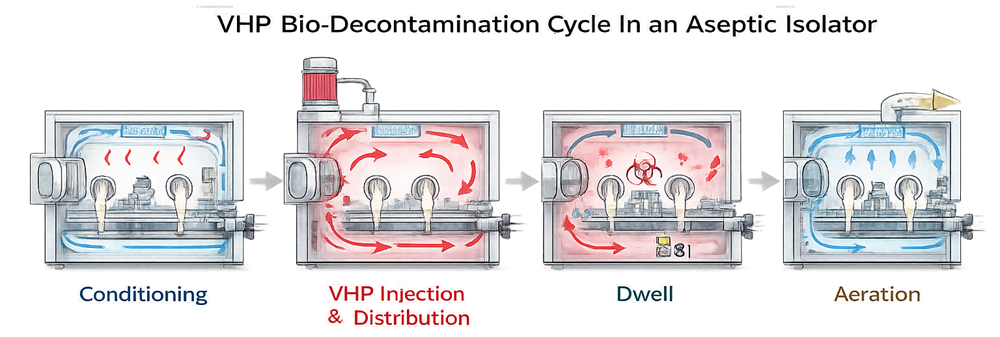
A complete cycle typically includes:
- Conditioning phase
- Sterilant injection and distribution
- Dwell period for microbial inactivation
- Aeration and residual removal
Cycle development requires mapping of hydrogen peroxide concentration distribution, temperature, humidity, and exposure time to ensure effective microbial reduction at worst-case locations. Biological indicators are placed in representative shadowed and low-flow areas to validate lethality.
Aeration must reduce residual hydrogen peroxide to predefined safe limits prior to production. Decontamination validation is a critical element of isolator qualification and must be supported by documented cycle development studies.
A validated bio-decontamination cycle prepares the isolator interior prior to aseptic processing.
6. Environmental Classification and Background Cleanroom
The internal isolator chamber is designed to maintain ISO 5 conditions over the critical processing area. Because the system is sealed and independently controlled, the surrounding cleanroom classification may be lower than that required for open systems, commonly ISO 7 or ISO 8 depending on process design and regulatory expectations.
However, background classification does not become irrelevant. The cleanroom must still provide controlled temperature, humidity, and external contamination management to support overall facility contamination control strategy.
Isolator performance must be demonstrated independently of room classification while ensuring appropriate pressure cascade relationships.
7. Qualification Strategy
Qualification of an isolator must demonstrate three integrated capabilities:
- Structural and mechanical integrity of the sealed enclosure
- Controlled and stable internal airflow and pressure performance
- Validated bio-decontamination effectiveness
Unlike open barrier systems, isolator qualification must address both environmental control and microbiological lethality within a closed system.
7.1 User Requirements Specification
The URS must define the contamination control strategy the isolator is intended to support. At minimum, it should specify:
- Intended aseptic process and product type
- Target sterility assurance objectives
- Positive or negative pressure regime
- Required internal airflow pattern and velocity range
- Transfer systems to be used, such as RTP or airlocks
- Bio-decontamination method, typically VHP
- Maximum allowable leak rate or enclosure integrity criteria
- Environmental monitoring strategy
- Intervention frequency and access limitations
The URS should clearly distinguish between product protection and containment requirements where applicable.
7.2 Installation Qualification
Installation Qualification confirms that the isolator is constructed and installed in accordance with approved design specifications.
IQ should include verification of:
- Panel assembly and sealed joints
- Gasket integrity and door alignment
- HEPA filter installation and seating
- Glove port installation and mechanical security
- Enclosure leak tightness testing methodology
- Integration of VHP generators, distribution piping, and injection ports
- Instrumentation for pressure, airflow, and concentration monitoring
- Alarm and interlock configuration
- Integration with facility utilities and exhaust systems
Leak integrity testing of the enclosure shell should be performed to confirm that the isolator meets predefined tightness criteria before proceeding to operational testing.
7.3 Operational Qualification
Operational Qualification verifies engineering performance and decontamination capability under controlled conditions. OQ must address:
Airflow and Pressure Control
- Downflow velocity mapping across critical processing zones
- HEPA filter integrity testing
- Pressure differential verification and alarm functionality
- Stability of airflow during defined static conditions
Enclosure Integrity
- Confirmed leak tightness of the isolator enclosure
- Glove integrity testing procedures and acceptance criteria
Bio-Decontamination Validation
- Development and mapping of VHP distribution
- Worst-case location identification
- Biological indicator placement strategy
- Demonstration of defined microbial reduction performance
- Verification of aeration effectiveness and residual limits
OQ establishes validated operating ranges for airflow, pressure, and decontamination cycle parameters. Acceptance criteria must be predefined and traceable to risk assessment and sterility assurance objectives.
7.4 Performance Qualification
Performance Qualification confirms that the fully integrated system maintains sterility assurance during routine and worst-case operating conditions. PQ must demonstrate that:
- The validated decontamination cycle consistently prepares the enclosure for aseptic processing
- Internal airflow remains stable during dynamic operations
- Pressure control remains within validated limits during interventions
- Transfer systems function without compromising enclosure integrity
Media fill studies must be conducted under isolator conditions following validated decontamination cycles. Representative and worst-case interventions, material transfers, glove manipulations, and door operations must be included.
The objective of PQ is to demonstrate that enclosure integrity, airflow control, decontamination effectiveness, and operator interaction collectively sustain aseptic conditions under realistic production scenarios.
8. Intervention and Transfer Systems
Because isolators are sealed, material and component transfer must occur through engineered interfaces. Common systems include rapid transfer ports, alpha-beta transfer systems, and material airlocks.
Transfer systems must preserve enclosure integrity and prevent contamination ingress. Glove replacement procedures must be controlled and validated to ensure that barrier integrity is not compromised during maintenance.
Intervention frequency should be minimized by design. Where interventions are necessary, procedures must be validated to confirm that airflow stability and contamination control are preserved.
9. Ongoing Control and Requalification
Isolator performance must be maintained through structured lifecycle control. Routine activities include HEPA filter integrity testing, airflow verification, pressure monitoring review, glove integrity testing, enclosure leak testing, and periodic verification of bio-decontamination cycle parameters.
Requalification is required following HEPA filter replacement, glove port replacement, seal repairs, structural modifications, control system updates, VHP system changes, or significant process alterations affecting airflow or transfer frequency.
Change control must evaluate impact on airflow stability, pressure relationships, decontamination effectiveness, and sterility assurance prior to implementation.
10. Regulatory Expectations
Regulatory expectations for isolators are anchored in contamination prevention, equipment suitability, and validated aseptic control. Under 21 CFR 211, sterile operations must be designed and maintained to prevent microbiological contamination, including appropriate aseptic area design under 211.42, equipment suitability under 211.63, proper maintenance under 211.67, and validated procedures to prevent contamination under 211.113(b). An isolator functions as critical aseptic processing equipment; therefore, its enclosure integrity, airflow performance, and bio-decontamination capability must be demonstrated, documented, and maintained within the validated state.
EU Annex 1 recognizes isolators as advanced barrier technology when supported by a documented Contamination Control Strategy. Expectations include validated bio-decontamination cycles, defined and minimized interventions, controlled transfer systems, airflow visualization studies, and evidence that the barrier remains effective during routine and worst-case conditions. Decontamination cycle development, biological indicator placement at worst-case locations, defined aeration endpoints, and transfer qualification are integral components.
Consensus standards support technical demonstration but do not replace GMP obligations. ISO 14644 provides particle classification methodology for clean environments, while industry guidance such as PDA technical reports informs aseptic barrier and decontamination practices. Compliance ultimately requires facility-specific qualification, risk-based justification, and ongoing lifecycle control tied to intended use.
Isolator compliance therefore depends on validated airflow performance, demonstrated decontamination effectiveness, controlled interventions and transfers, and structured integrity and change management throughout the equipment lifecycle.