
Load Development Strategy
Steam sterilization is validated for defined load configurations — not for the chamber alone. Load development establishes the worst-case conditions under which sterilization must be demonstrated. A poorly defined load results in unreliable qualification data, unexpected PQ failures, and defensibility issues during inspection.
1. Purpose of Load Development
The objective of load development is to:
- Identify worst-case thermal conditions
- Define reproducible load configurations
- Establish standard load diagrams
- Justify biological indicator placement
- Support thermocouple mapping strategy
Load development bridges engineering principles and qualification execution.
2. Load Categories
Load behavior depends heavily on material and configuration. Common categories include:
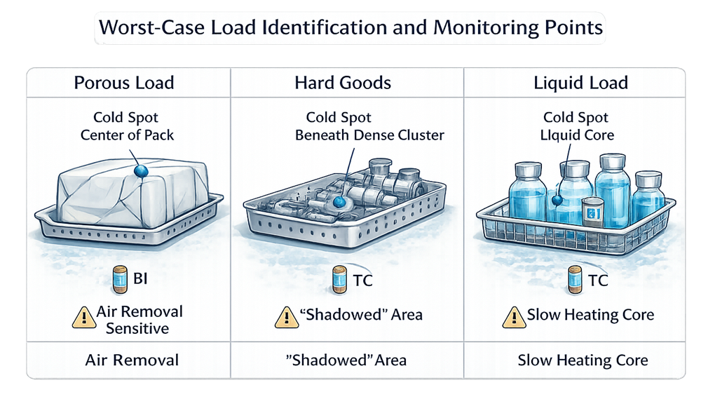
2.1 Porous Loads
Examples:
- Textiles
- Gown packs
- Gauze
- Filters
- Wrapped trays
Risks:
- Air retention
- Delayed heat penetration
- Internal cold spots
Porous loads are typically air removal sensitive.
2.2 Hard Goods
Examples:
- Stainless steel components
- Instruments
- Non-porous assemblies
Risks:
- Shadowing
- Condensate pooling
- Surface heat transfer limitations
2.3 Liquids
Examples:
- Aqueous solutions
- Media fills
- Filled containers
Risks:
- Slow heat-up due to convection
- Core temperature lag
- Container closure integrity
Liquids often represent worst-case lethality delivery due to internal heat transfer limitations.
3. Worst-Case Load Determination
Worst-case conditions may involve:
- Maximum mass
- Maximum density
- Tightest packaging
- Largest container size
- Maximum fill volume
- Most restrictive air removal geometry
Worst-case does not always mean largest load. It means most difficult to sterilize. Engineering assessment must consider:
- Heat penetration resistance
- Air entrapment potential
- Material adsorption characteristics
- Historical cycle performance
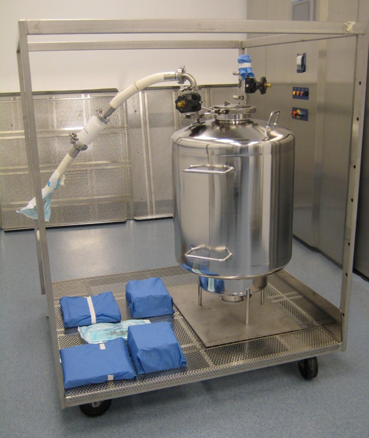
Equipment Assembly Load Example
Example of equipment assembly load during development study: Stainless steel tank and associated fill-machine components arranged for steam sterilization load development. Complex geometries, internal volumes, and connected assemblies require deliberate evaluation of cold spots and thermocouple placement strategy.
Typical examples include:
- Filling machine components
- Process tanks and manifolds
- Hose assemblies
- Sterilizing filter housings
Primary risks:
- Internal lumen cold spots
- Condensate retention
- Shadowed or shielded surfaces
- Slow heat penetration within enclosed volumes
4. Load Configuration Control
Each validated load must have:
- Documented diagram
- Defined orientation
- Specified tray arrangement
- Maximum load limits
- Acceptable variability range
Routine production must replicate validated configuration. Informal loading practices undermine qualification integrity.
5. Cold Spot Identification
Cold spots may exist:
- Within porous packs
- In densest region of trays
- At container core in liquid loads
- At drain location
Thermocouple placement during development identifies:
- Slowest heating locations
- Air retention zones
- Areas requiring biological indicator placement
Load development informs thermocouple mapping — not the reverse.
6. Biological Indicator Strategy
BI placement must reflect:
- Worst-case penetration points
- Air removal sensitive areas
- Densest load regions
BI placement must be justified, not arbitrary.
7. Documentation Expectations
Load development should produce:
- Engineering rationale
- Defined worst-case loads
- Approved load diagrams
- Risk-based justification
- Mapping strategy linkage
Regulators expect documented logic — not “this is how we’ve always loaded it.”