
Lyophilization Interface with Aseptic Filling Systems
Lyophilized drug products introduce a controlled exposure phase between filling and final container closure. Unlike liquid products that are stoppered and sealed immediately after filling, lyophilized vials remain partially stoppered and unsealed until completion of the freeze-drying cycle.
The interface between the filling line and the lyophilizer is therefore a defined contamination control segment within aseptic processing. Sterility assurance during this phase depends on environmental protection, exposure time control, mechanical stability of partially inserted stoppers, and validated transfer procedures.
This article addresses the lifecycle control and qualification of that interface. Freeze-drying cycle development, thermal mapping, and primary/secondary drying theory are excluded.
Prerequisite:
The lyophilizer must be fully qualified prior to interface validation. Chamber leak testing, vacuum system performance, thermal mapping, stoppering mechanism qualification, and control system validation must be complete and approved. Interface validation assumes the lyophilizer is already in a validated state.
1. Definition of the Interface
As illustrated in the ISO 5 Protection and Exposure Window Map, the lyophilization interface begins at the moment of needle withdrawal and ends at lyophilizer chamber door closure.
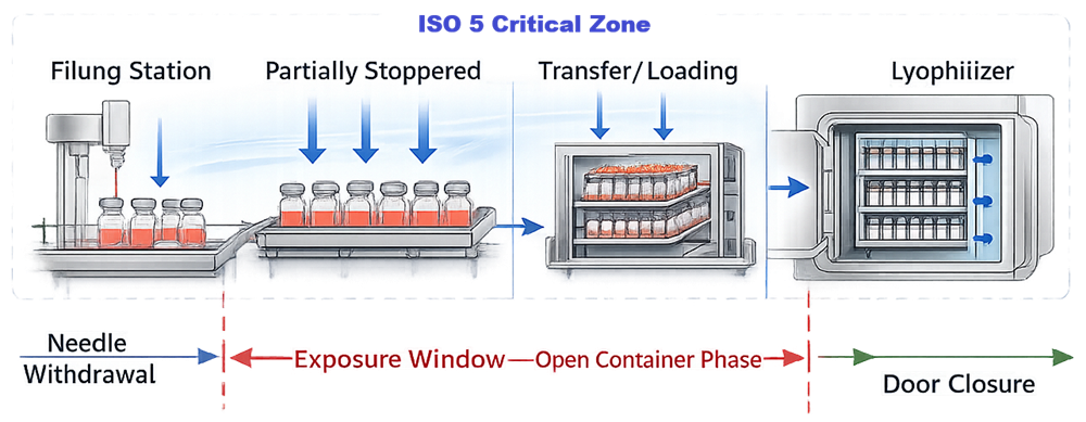
On the diagram, the left boundary of the exposure window is marked at Needle Withdrawal. The right boundary is marked at Door Closure. The red bracket labeled Exposure Window – Open Container Phase defines this interval.
During this defined exposure window:
• Vials are partially stoppered but not sealed
• The stopper does not provide a microbial barrier
• The product surface remains exposed to the environment
• Sterility assurance depends exclusively on validated ISO 5 unidirectional airflow
Mechanical container closure has not yet occurred. The sterile boundary is environmental and time-dependent.
This interval must be formally identified in process documentation as a controlled exposure step. The following parameters must be predefined and validated:
• Maximum allowable exposure duration
• Environmental classification requirements
• Airflow protection criteria
• Door-open time limits
• Acceptable interruption handling procedures
The interface is therefore not simply a transfer operation. It is a validated contamination control phase bounded by needle withdrawal and chamber closure, as shown in the diagram.
2. Contamination Control Strategy
2.1 Sterile Boundary Continuity
Sterile boundary continuity must be maintained from filling through chamber closure.
In isolator systems, as illustrated in the Docking and Sterile Boundary Continuity model, the interface is achieved through dock-to-dock transfer between the filling isolator and the lyophilizer chamber. The docking flange and transfer port seals define a continuous enclosed sterile boundary. These seals must prevent environmental ingress and maintain validated pressure differentials to preserve sterility throughout the transfer.
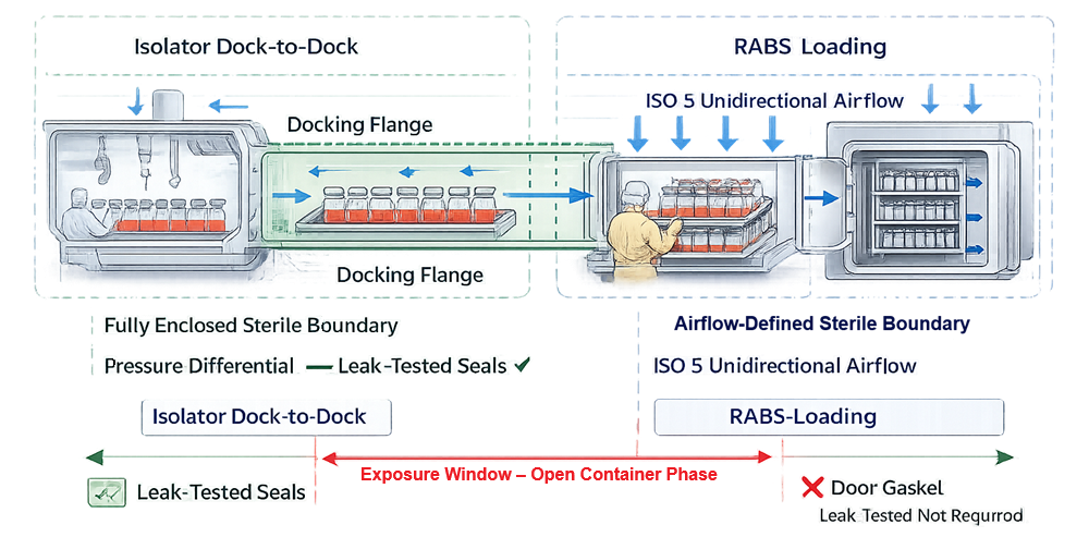
In RABS systems, sterility depends on unidirectional airflow. Airflow protection over exposed vial openings must be demonstrated during dynamic loading.
The sterile boundary at this stage is environmental and time-dependent, not mechanical.
2.2 Airflow Protection During Loading
Airflow visualization studies must demonstrate:
• First-air protection over vial openings
• No turbulence from tray movement
• No airflow shadowing caused by carts or operators
• Stability during door opening
Testing must represent worst-case operational configuration.
2.3 Open Vial Exposure Time
Maximum allowable exposure time must be defined and validated.
This includes:
• Time from fill completion to loading
• Maximum queue length
• Loading duration
• Door-open time
• Simulated equipment stops
Exposure validation must be included in process simulation.
Extended exposure increases contamination probability independent of filling performance.
2.4 Stopper Geometry and Mechanical Stability
Partial stopper insertion creates a defined configuration required for vapor escape during drying.
Interface controls must ensure:
• Reproducible insertion depth
• Consistent insertion force
• Proper alignment
• Stability during transfer vibration
Failure modes include over-insertion, under-insertion, tilt, and displacement.
Mechanical control at this stage directly affects both sterility and container closure integrity.
2.5 Regulatory Alignment
The lyophilization interface represents an aseptic exposure phase and is subject to the same regulatory expectations as any ISO 5 critical operation.
Applicable regulatory frameworks include:
• 21 CFR 211.113 – Control of microbiological contamination
• 21 CFR 211.42 – Design and construction features
• 21 CFR 211.63 – Equipment design and maintenance
• EU GMP Annex 1 – Contamination Control Strategy and aseptic processing requirements
Annex 1 explicitly requires that open container handling and transfers between processing steps be protected under appropriate environmental conditions. The lyophilization loading phase falls within this requirement.
Regulators expect documented evidence that:
• ISO 5 conditions are maintained during transfer
• Open exposure duration is justified and validated
• Airflow patterns protect sterile product
• Environmental monitoring includes the loading interface
• Media simulation incorporates worst-case loading conditions
Failure to validate this interface is frequently cited in inspection observations where media fill excludes loading or where airflow during transfer has not been demonstrated under dynamic conditions.
The interface must therefore be defined within the facility’s Contamination Control Strategy and supported by documented risk assessment, qualification evidence, and ongoing performance monitoring.
3. Qualification of the Interface
The interface must be qualified as a distinct contamination control segment bridging filling and lyophilization.Rather than repeating full equipment qualification structure, qualification focuses on interface-specific controls.
3.1 Airflow and Environmental Qualification
Qualification must include:
• Dynamic smoke studies during loading
• Verification of ISO 5 conditions during tray movement
• Environmental monitoring placement at transfer zone
• Validation of airflow recovery after door closure
Testing must challenge worst-case loading conditions.
3.2 Exposure Time Validation
The maximum validated exposure duration must be established through:
• Worst-case batch size
• Longest loading sequence
• Simulated minor equipment interruptions
• Maximum allowable door-open interval
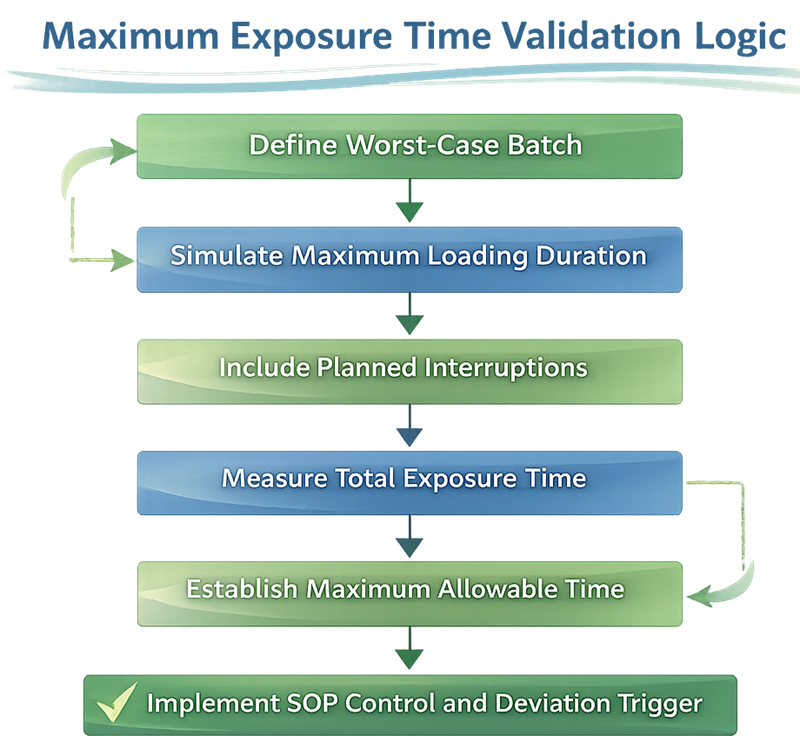
The diagram below illustrates the structured logic used to establish and control the maximum allowable exposure time during the lyophilization interface. Exposure limits must be derived from risk assessment, worst-case operational conditions, and validated simulation data rather than informal operational practice.
The validated limit must be incorporated into batch records and SOPs.
3.3 Docking and Seal Integrity
For isolator-integrated systems:
• Dock seal leak testing
• Pressure differential monitoring
• Defined leak rate acceptance criteria
For RABS systems:
• Door gasket integrity verification
• Chamber leak rate confirmation
Mechanical integrity supports environmental sterility control.
3.4 Stopper Position Verification
Qualification must demonstrate:
• Reproducibility of partial insertion height
• Stability during full-batch transfer
• Acceptable variability limits
Measurement studies and worst-case vibration challenges may be required.
3.5 Integrated Media Simulation
If lyophilization is part of the commercial process, media fill must include:
• Partial stoppering
• Transfer and loading
• Worst-case exposure duration
• Chamber closure
Excluding this interface from media simulation creates a validation gap.
3.6 Post-Cycle Closure Confirmation
Although final stoppering occurs within the qualified lyophilizer, the interface qualification must confirm:
• Uniform stopper compression
• No stopper pop-up
• Acceptable container closure integrity performance
This links environmental exposure control to final mechanical seal performance.
4. Lifecycle Control and Continued Verification
Interface validation does not end at initial qualification.
Ongoing monitoring should trend:
• Loading duration
• Door seal alarms
• Environmental monitoring at transfer zone
• Stopper seating deviations
• Operator intervention frequency
Periodic review must assess whether exposure time remains within validated limits under actual production conditions.
5. Change Control and Requalification Triggers
Requalification may be required following:
• Lyophilizer relocation
• Barrier system modification
• Loading automation change
• Increased batch size
• Significant airflow system maintenance
• Stopper or vial design change
Impact assessment must determine whether airflow, exposure time, or mechanical stability are affected.
Conclusion
The lyophilization interface represents a defined exposure phase within aseptic fill-finish operations. Sterility assurance during this period depends on airflow protection, exposure time control, docking integrity, stopper stability, and integration into media simulation.
The lyophilizer must be qualified first. Interface validation then confirms that sterility is maintained across the transition from filling to chamber closure and final stoppering.
Filling and freeze-drying are separate unit operations. Sterility assurance across their interface is continuous and must be managed through structured lifecycle control.