
Lyophilization System Design and Critical Components
1. Introduction
Lyophilization systems are engineered to remove water from a frozen product through sublimation under controlled temperature and pressure conditions. In pharmaceutical manufacturing, the lyophilizer functions as a pressure vessel, a thermal control system, a vacuum system, and, in aseptic applications, part of the sterile boundary.
System design directly influences residual moisture, cake structure, reconstitution time, and container closure integrity. Temperature non-uniformity, vacuum instability, or condenser overload cannot be corrected by recipe adjustment alone. These are engineering problems.
This article defines the mechanical, thermal, vacuum, and control architecture of pharmaceutical lyophilization systems and establishes the technical baseline required before qualification activities begin.
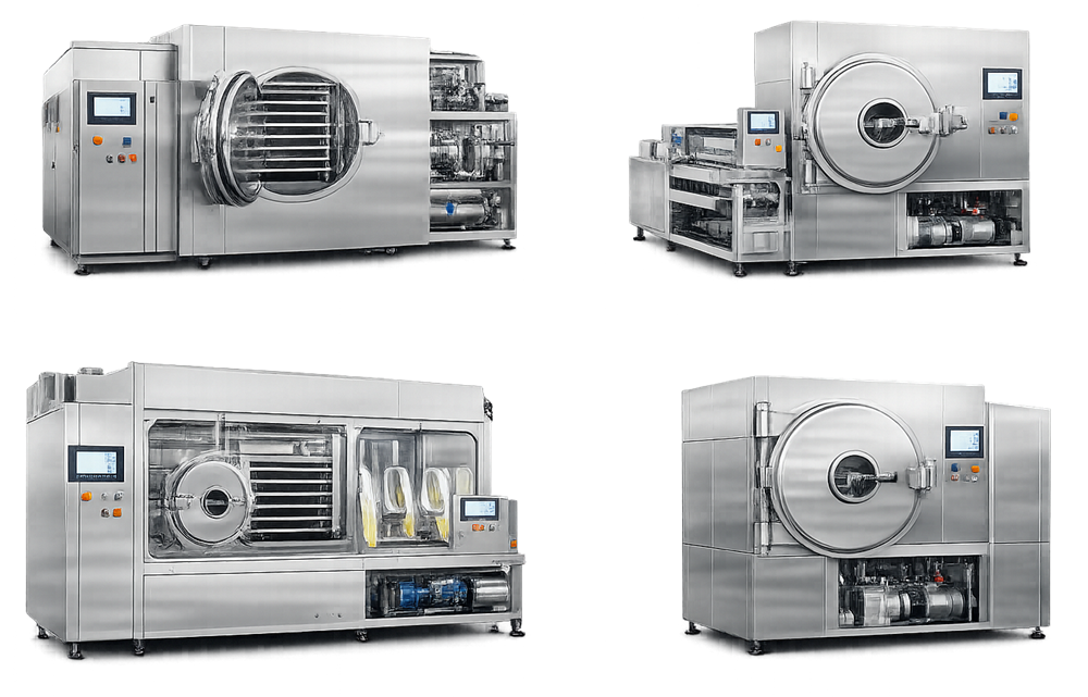
Modern pharmaceutical lyophilizers are engineered systems that integrate vacuum generation, refrigeration, controlled heat transfer, and automated process control within a single pressure-rated assembly. Production-scale units are typically constructed from stainless steel and include an insulated chamber door, integrated control panel, and enclosed refrigeration and vacuum modules. While the exterior presents a clean, modular configuration suitable for GMP environments, the internal architecture incorporates tightly controlled thermal and pressure systems required to support reproducible freeze-drying performance.
2. Overall System Architecture
A pharmaceutical lyophilization system consists of four integrated subsystems:
- Product chamber with temperature-controlled shelves
- External condenser for vapor capture
- Vacuum generation system
- Refrigeration and thermal regulation system
These subsystems operate as a coordinated unit controlled by programmable logic and monitored by pressure and temperature instrumentation.
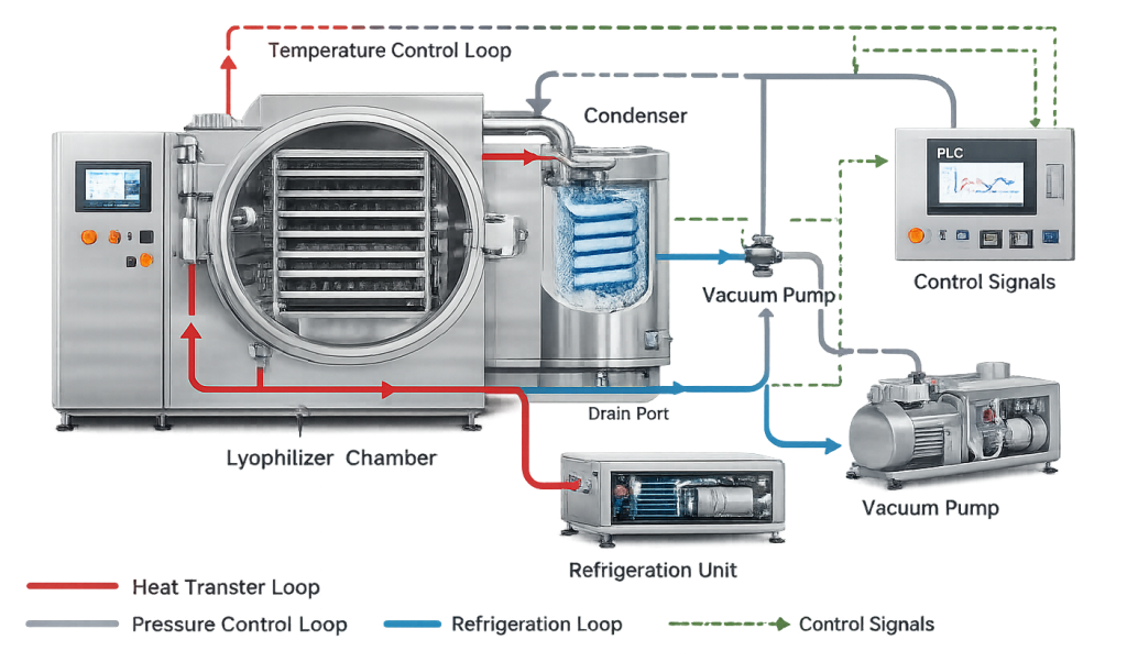
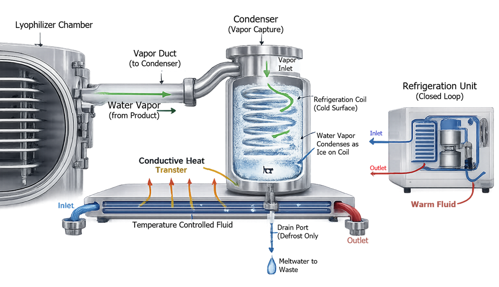
The chamber contains the product. Shelves provide conductive heat transfer. The condenser traps sublimated vapor. The vacuum system establishes low-pressure conditions required for sublimation. The refrigeration system independently regulates shelf and condenser temperatures. Stable vapor flow from chamber to condenser is fundamental. Any restriction or instability affects primary drying performance.
A lyophilizer operates as an integrated system composed of chamber, condenser, refrigeration unit, vacuum system, and control architecture. The illustration should depict subsystem boundaries and the direction of vapor flow during primary drying. This visualization reinforces that drying performance depends on coordinated interaction between thermal, mechanical, and pressure-control elements.
3. Chamber Design and Construction
The chamber is a vacuum-rated stainless steel vessel, typically fabricated from 316L stainless steel with an internal surface finish compatible with cleaning and sterilization.
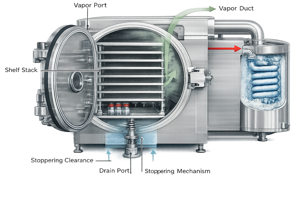
The internal chamber geometry influences vapor flow resistance, shelf alignment, and drainability. The illustration should show the vertical shelf stack, vapor outlet to the condenser, and door sealing interface. This view clarifies how chamber configuration affects drying uniformity and vacuum stability.
3.1 Structural and Mechanical Design
Critical design characteristics include:
- Structural integrity under full vacuum
- Door sealing reliability
- Gasket material compatibility with thermal cycling
- Resistance to long-term mechanical deformation
The chamber must maintain vacuum integrity throughout freezing and drying phases.
3.2 Cleanability and Sterility Considerations
Design must ensure:
- Smooth, cleanable internal surfaces
- Minimal crevices and dead legs
- Complete drainability
- Compatibility with CIP and SIP where applicable
Chamber geometry must support effective cleaning solution coverage and complete condensate removal. In aseptic configurations, the chamber and associated piping must allow validated steam sterilization without creating cold spots, trapped air, or residual moisture pockets.
Surface finish, weld quality, and internal transitions directly affect cleanability and sterility assurance. Poor mechanical design at this level cannot be compensated by extended cleaning or sterilization cycles.
4. Shelf Assembly and Heat Transfer System
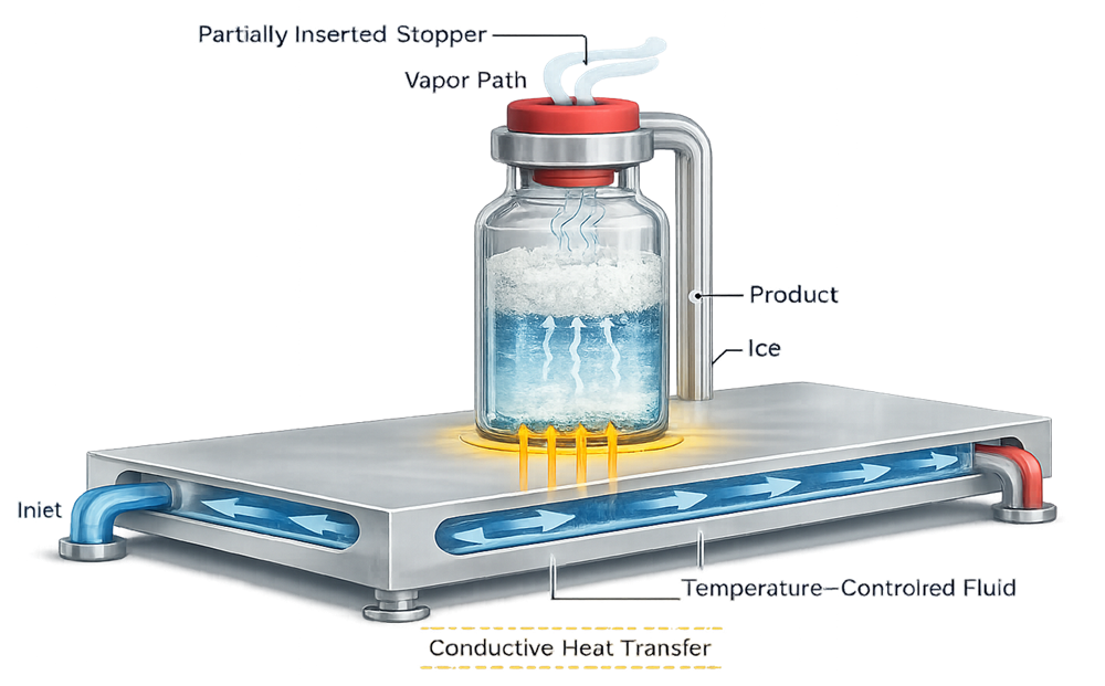
Shelves are the primary heat transfer interface between system and product. Heat transfer occurs predominantly by conduction through vial contact with shelf surfaces.
Heat is transferred from the temperature-controlled shelf to the product primarily by conduction through the vial base. The illustration should demonstrate the relationship between shelf temperature, vial contact, and product temperature. It should visually explain why shelf flatness and temperature uniformity are critical engineering requirements.
4.1 Thermal Regulation
Each shelf contains internal channels circulating a controlled heat transfer fluid. The external thermal control unit must provide:
- Precise temperature control
- Controlled ramp rates
- Rapid cooling capability for freezing
4.2 Uniformity Requirements
Critical parameters include:
- Shelf flatness
- Thermal fluid distribution
- Edge-to-center temperature variation
- Shelf-to-shelf consistency
Temperature non-uniformity directly results in product temperature variability. Exceeding collapse temperature during primary drying compromises cake structure.
4.3 Mechanical Tolerances
Shelf alignment affects stoppering compression accuracy. Vertical travel must be precise to ensure uniform stopper seating.
5. Refrigeration and Condenser System
The condenser captures sublimated water vapor by freezing it onto cold surfaces. Effective sublimation requires condenser temperature significantly below product temperature.
During primary drying, water vapor generated by sublimation exits the lyophilizer chamber and flows through the vapor duct into the condenser. The condenser surface is maintained at a temperature significantly lower than the product temperature, creating a thermodynamic driving force that directs vapor away from the chamber. Upon contact with the cold coils, water vapor deposits as ice, thereby removing mass from the chamber and sustaining low-pressure conditions required for continued sublimation. During the defrost phase, accumulated ice is melted and drained from the system. This controlled, unidirectional vapor transport path is fundamental to pressure stability, drying efficiency, and overall process reproducibility.
5.1 Condenser Capacity
Design considerations include:
- Condenser surface area
- Ice holding capacity
- Minimum achievable condenser temperature
- Refrigeration compressor sizing
Undersized condensers cause chamber pressure instability and extended drying time.
5.2 Defrost and Drainage
The system must allow:
- Controlled defrost cycles
- Effective condensate removal
- Prevention of re-evaporation into the chamber
Refrigeration systems must be sized for worst-case vapor loads during peak primary drying.
6. Vacuum System Design
The vacuum system establishes and maintains low pressure required for sublimation.
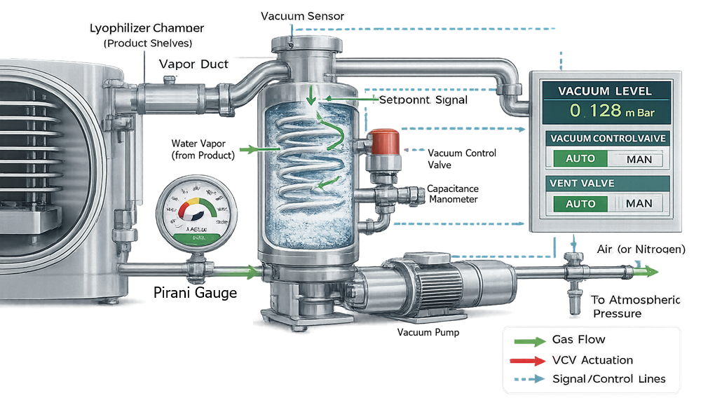
Chamber pressure control during lyophilization is achieved through coordinated measurement and modulation of the vacuum system. Water vapor generated during sublimation is removed by the vacuum pump, while a control valve regulates chamber pressure to a defined setpoint. Accurate pressure measurement is critical and is typically accomplished using two complementary instruments: a capacitance manometer and a Pirani gauge.
The capacitance manometer provides gas-independent, absolute pressure measurement and serves as the primary control reference during primary and secondary drying. In contrast, the Pirani gauge measures thermal conductivity of the gas and is therefore sensitive to water vapor concentration. The divergence between Pirani and capacitance readings during primary drying provides process insight and can support endpoint determination.
Together, these instruments enable stable pressure control, ensure reproducible sublimation conditions, and maintain the thermodynamic driving force required for efficient moisture removal.
6.1 Core Components
Typical components include:
- Vacuum pump or multi-stage pump train
- Isolation valves
- Throttle control valve
- Capacitance manometer
- Pirani gauge
6.2 Pressure Measurement Strategy
Capacitance manometers provide gas-independent pressure measurement. Pirani gauges are gas-dependent and respond to vapor concentration changes. Both are necessary for reliable process monitoring.
6.3 Leak Rate and Stability
Excessive leakage increases drying time and destabilizes pressure control. The system must achieve required ultimate pressure within defined pull-down time.
7. Stoppering Mechanism
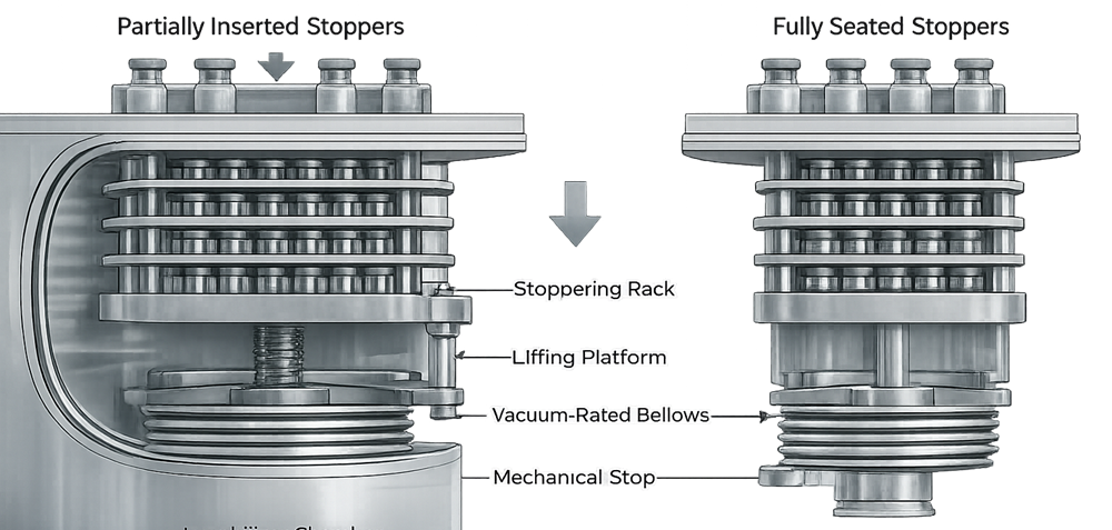
In aseptic systems, vials are partially stoppered prior to lyophilization. At cycle completion, shelves descend to fully seat stoppers.
At the completion of secondary drying, the lyophilizer performs a controlled mechanical stoppering step to fully seat partially inserted stoppers. The shelves descend vertically, contacting the stopper flange and applying uniform axial compression until a defined mechanical travel stop is reached. This displacement-controlled motion ensures consistent final seating height across all vials.
The actuator that drives this movement is isolated from the chamber by vacuum-rated bellows, allowing motion without compromising chamber pressure integrity. Stoppering typically occurs under vacuum or controlled inert gas backfill to preserve product stability and sterility. Precision in vertical alignment, travel control, and mechanical stops is essential to prevent tilted stoppers, incomplete seating, or container closure integrity failures.
7.1 Mechanical Requirements
The stoppering system must ensure:
- Uniform vertical compression
- Accurate shelf travel
- Minimal vial movement
- Repeatable alignment
Mechanical misalignment results in incomplete stopper seating or vial damage.
7.2 Vacuum and Gas Backfill Control
Stoppering may occur under vacuum or inert gas backfill. Pressure equalization must be controlled to avoid disturbing dried product structure.
8. Instrumentation and Control Architecture
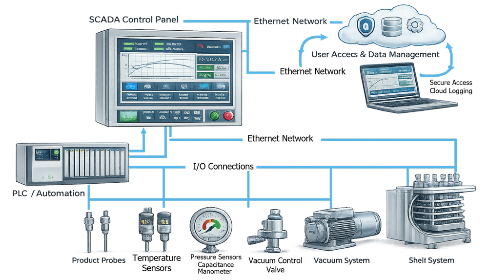
The control system integrates thermal regulation, vacuum control, refrigeration management, and alarm logic.
Thermal regulation, vacuum control, and alarm management are coordinated through programmable logic and operator interface systems. The illustration should depict the separation of temperature and pressure control loops and their integration within the PLC boundary.
8.1 Critical Instrumentation
Key instruments include:
- Shelf temperature sensors
- Product thermocouples
- Capacitance manometer
- Pirani gauge
- Refrigeration temperature sensors
- Valve position feedback
8.2 Control Logic and Safeguards
The control system must prevent incompatible states, such as:
- Shelf heating without adequate vacuum
- Stoppering during unstable pressure
- Operation beyond condenser capacity
In regulated environments, the system must support user access control, audit trails, and secure data storage.
9. Clean-in-Place and Steam-in-Place Integration
For aseptic applications, lyophilizers must integrate with cleaning and sterilization utilities.
9.1 Cleaning Design
Cleaning systems must ensure:
- Adequate spray coverage
- Complete drainability
- Elimination of trapped residues
9.2 Sterilization Design
Steam sterilization requires:
- Effective air removal
- Uniform steam distribution
- Proper condensate evacuation
- Sensor placement for cold spot detection
Cold spots or trapped condensate compromise sterility assurance.
10. Design Risks and Engineering Failure Modes
Common design-related risks include:
- Shelf temperature non-uniformity
- Insufficient condenser capacity
- Vacuum instability
- Excessive leak rate
- Stoppering misalignment
- Instrument drift
- Inadequate drainage
These risks must be evaluated during design review and addressed before qualification.
11. Position Within the Validation Lifecycle
Lyophilization system design establishes the engineering boundaries within which process validation will occur. The next lifecycle stage, Lyophilization System Qualification, verifies that the installed system performs within defined mechanical, thermal, and vacuum specifications.
Only after equipment capability is demonstrated can a product-specific lyophilization cycle be validated with confidence.