
Lyophilization System Qualification
1. Introduction
Lyophilization system qualification verifies that the installed freeze-dryer performs according to its defined mechanical, thermal, and vacuum design specifications. Qualification confirms equipment capability independent of any specific product formulation.
The objective is to demonstrate that the system can achieve and maintain controlled shelf temperature, chamber pressure, condenser performance, and stoppering function within predefined acceptance criteria. Only after equipment capability is established can product-specific cycle validation be considered reliable.
2. Qualification Strategy and Lifecycle Position
Lyophilization qualification follows a structured lifecycle beginning with design confirmation and progressing through installation, operational, and performance verification. The illustration should depict the progression from DQ to IQ, OQ, and Equipment PQ, emphasizing that equipment capability must be demonstrated before product-specific process validation. This reinforces separation between equipment qualification and process qualification.
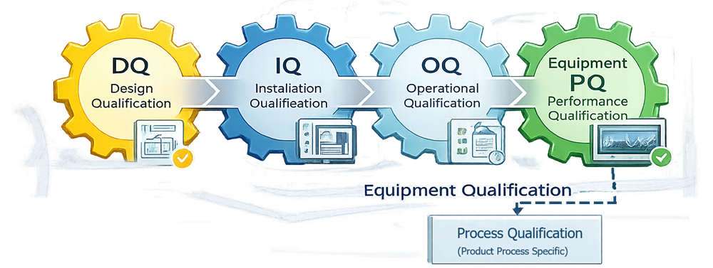
Lyophilization qualification follows the standard equipment lifecycle:
- Design Qualification (DQ)
- Installation Qualification (IQ)
- Operational Qualification (OQ)
- Performance Qualification (Equipment PQ)
This article focuses on IQ, OQ, and equipment-level PQ.
System qualification must be completed prior to process performance qualification of any product.
3. Installation Qualification (IQ)
Installation Qualification confirms that the lyophilizer is installed in accordance with approved design documents and manufacturer specifications.
3.1 Utilities Verification
Verify and document:
- Electrical supply
- Cooling water supply
- Compressed air
- Vacuum connections
- Clean steam, if applicable
- Drainage systems
Utility parameters must meet design requirements.
3.2 Mechanical Installation
Confirm:
- Chamber integrity
- Shelf stack alignment
- Bellows installation
- Condenser configuration
- Refrigeration connections
- Stoppering assembly installation
3.3 Instrumentation and Calibration
Verify installation and calibration of:
- Shelf temperature sensors
- Product thermocouples
- Capacitance manometer
- Pirani gauge
- Control valves
- Pressure transmitters
Calibration certificates must be traceable.
3.4 Control System Verification
Document:
- PLC software version
- HMI configuration
- Alarm configuration
- Security and user access controls
- Data recording functionality
This establishes configuration control prior to operational testing.
4. Operational Qualification (OQ)
Operational Qualification verifies that the system operates within defined engineering limits under controlled test conditions.
4.1 Shelf Temperature Mapping
Shelf temperature mapping verifies thermal uniformity across the entire shelf surface and between shelves. The illustration should show a top-down grid of probe locations distributed across a shelf, including edge and center positions. This visual supports understanding of how mapping defines the thermal operating envelope and identifies hot or cold spots.
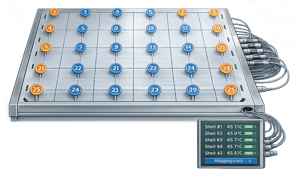
Demonstrate:
- Temperature uniformity across each shelf
- Shelf-to-shelf consistency
- Ramp rate accuracy
- Steady-state stability
Acceptance criteria must define maximum allowable deviation.
4.2 Chamber Leak Rate Test
The rate-of-rise test confirms chamber integrity by isolating the system under vacuum and measuring pressure increase over time. The illustration should depict chamber isolation, vacuum valve closure, and a pressure trend line increasing gradually. This demonstrates how leak rate is calculated and why chamber tightness is critical for pressure stability.
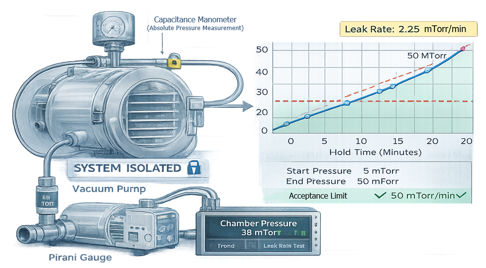
Perform vacuum hold or rate-of-rise testing to confirm:
- Maximum allowable leak rate
- Stability of pressure under isolation
Leak integrity directly affects drying reproducibility.
4.3 Vacuum Pull-Down Test
Verify:
- Time required to reach target vacuum
- Stability at setpoint
- Proper operation of vacuum control valve
4.4 Condenser Capacity Verification
Confirm condenser performance by:
- Demonstrating minimum achievable temperature
- Verifying refrigeration stability
- Confirming ice holding capacity under simulated load
4.5 Stoppering Function Test
Stoppering verification confirms consistent vertical travel and final seating position across the shelf area. The illustration should show measurement of final stopper height and defined mechanical travel limits. This reinforces the relationship between mechanical precision and container closure integrity.
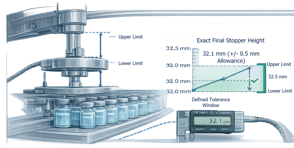
Demonstrate:
- Uniform shelf travel
- Final seating height consistency
- Absence of vial tipping or misalignment
This confirms mechanical precision.
4.6 Alarm and Interlock Challenges
Verify that:
- High/low temperature alarms function
- Pressure deviation alarms trigger
- Safety interlocks operate correctly
- Incompatible states are prevented
Alarm logic must be tested, not assumed.
4.7 Operational Qualification (OQ) Test Matrix – Lyophilization System
The following Operational Qualification test matrix defines the structured verification activities required to demonstrate that the lyophilization system operates within its specified mechanical, thermal, vacuum, and control limits. Each test confirms a critical functional aspect of the equipment independent of any specific product formulation. The matrix establishes objective test intent, defined acceptance criteria, required data collection, and instrumentation dependencies.
Successful execution of these tests demonstrates that the system is capable of stable shelf temperature control, reliable pressure regulation, adequate condenser performance, precise stoppering operation, and compliant data recording. Completion of OQ establishes documented evidence that the lyophilizer is ready for equipment-level performance qualification and subsequent process validation activities.
| OQ Test Name | Objective | Preconditions | Test Method Summary | Acceptance Criteria | Data and Records | Instruments and Controls | Notes |
|---|---|---|---|---|---|---|---|
| Utilities Functional Verification | Confirm required utilities support operation under load conditions | IQ complete, utilities released | Verify utility presence, operating ranges, alarms, and interlocks during operation | All utilities within specified ranges and alarms function correctly | Utility readings, alarm logs, deviation log | Facility meters, PLC trends | Include power quality if required |
| Control System Start-Up and Mode Control | Verify correct start-up, shutdown, and mode transitions | IQ software baseline established | Execute start-up, standby, run, defrost, and shutdown sequences | All transitions execute without fault; no invalid states allowed | Event log, audit trail, screenshots | PLC, HMI, historian | Confirms state machine integrity |
| User Access and Audit Trail Verification | Verify role-based access and audit trail capture | User roles configured | Attempt restricted actions by role; verify audit trail for setpoint and recipe changes | Access restricted per role; audit trail complete and time-stamped | Audit trail export, user list, screenshots | HMI security configuration | Confirm system time synchronization |
| Shelf Temperature Control Accuracy | Verify shelf temperature accuracy and stability | Calibrated shelf sensors | Step shelves to defined setpoints and hold; trend stability | Temperature within defined accuracy and stability limits | Trend data, summary tables | Shelf RTDs, control loop outputs | Setpoints based on URS operating range |
| Shelf Ramp Rate Verification | Verify heating and cooling ramp performance | Shelf control verified | Execute programmed ramps up and down; compare actual to command | Ramp rate within tolerance; no unacceptable overshoot | Trend plots, ramp calculations | PLC trend data, RTDs | Include worst-case ramp scenario |
| Shelf Temperature Uniformity Mapping | Verify temperature uniformity across shelves | Mapping probes calibrated | Map steady-state temperatures at low, mid, and high setpoints | Uniformity within defined delta across all mapped points | Mapping report, probe calibration certificates | Calibrated mapping system | Defines validated operating envelope |
| Chamber Pressure Control Stability | Verify stable pressure control at defined setpoints | Vacuum system operational | Control pressure at multiple setpoints; trend stability | Pressure within tolerance; no sustained oscillation | Pressure trends, valve position data | Capacitance manometer, control valve | Covers primary drying range |
| Vacuum Pull-Down Performance | Verify time to reach target vacuum | Chamber sealed and at atmosphere | Pull down to target pressure; record time and stability | Pull-down time within limit; stable at target | Time-to-target data, trends | Vacuum pump, pressure sensors | Confirms pump capacity |
| Leak Rate Test (Rate of Rise) | Verify chamber leak integrity | Chamber at target vacuum | Isolate chamber; record pressure rise over defined period | Leak rate below defined maximum | Calculations, pressure trend data | Capacitance manometer | Repeat after maintenance |
| Instrument Agreement (Capacitance vs Pirani) | Verify proper behavior of dual pressure instruments | Both gauges calibrated | Compare readings under stable conditions | Signals stable; expected relationship observed | Trend overlays | Capacitance manometer, Pirani gauge | Supports future endpoint logic |
| Condenser Minimum Temperature Verification | Confirm condenser reaches required minimum temperature | Refrigeration system operational | Drive condenser to minimum setpoint; hold and trend | Meets defined minimum temperature and stability | Temperature trends | Condenser temperature sensors | Acceptance per URS |
| Condenser Capacity Challenge | Verify condenser performance under simulated vapor load | Safe simulation method approved | Introduce controlled water load; monitor pressure and condenser performance | Maintains temperature and pressure control within limits | Trend data, load documentation | Condenser sensors, pressure instruments | Conservative simulation only |
| Defrost and Drain Function | Verify defrost cycle and drainage | Condenser iced or simulated | Execute defrost sequence; verify meltwater removal | Defrost completes; no pooling or alarms | Event log, visual confirmation | PLC sequence controls | Include drain heat tracing if present |
| Stoppering Travel and Seating Repeatability | Verify uniform vertical travel and seating height | Stoppering system installed | Execute stoppering cycle with surrogate vials; measure seating height | Seating height within tolerance; no tilted stoppers | Measurements, documentation | Shelf position feedback | Critical for closure integrity |
| Vacuum Break and Backfill Control | Verify controlled venting and inert gas backfill | Gas supply available | Execute vacuum break; monitor rate and stability | Target pressure reached without unacceptable overshoot | Trend data, event log | Vent valve, pressure sensors | Protects cake structure |
| Alarm and Interlock Challenge | Verify critical alarms and safety interlocks | Baseline configuration approved | Force defined fault conditions; verify response | Correct alarm activation and interlock function | Alarm logs, screenshots | PLC logic, HMI | Includes high temp, pressure, vacuum loss |
| Power Loss and Safe State | Verify system behavior during power interruption | Risk assessment completed | Simulate power loss; observe system transition and recovery | Safe state achieved; event recorded | Event log, restart records | PLC, UPS if present | Critical for data integrity |
| Data Capture and Record Integrity | Verify completeness and retrievability of electronic data | Historian configured | Run representative sequence; export and review records | Complete, time-synced, attributable data | Export files, audit trail | Historian system | Confirm backup and retention |
5. Equipment Performance Qualification (PQ)
Equipment-level PQ demonstrates reproducible performance under simulated load conditions.
5.1 Empty Chamber Mapping
Establish baseline thermal behavior without load.
5.2 Loaded Chamber Thermal Mapping
Use surrogate vials or water-filled containers to simulate load. Verify:
- Temperature uniformity under load
- Shelf recovery performance
- Pressure stability during simulated drying
5.3 Worst-Case Configuration Testing
Test:
- Maximum shelf loading
- Edge-of-shelf positions
- Maximum condenser load
- Long-duration cycles
This defines the validated operating envelope.
6. Acceptance Criteria
Acceptance criteria define the measurable limits that determine whether the lyophilization system performs in accordance with design intent and user requirements. These criteria must be established prior to protocol approval and execution. Post-execution adjustment of limits undermines validation integrity. Acceptance limits shall be derived and justified using one or more of the following:
- Manufacturer design specifications
- User Requirement Specification (URS)
- Engineering tolerances and system capability
- Risk assessment outputs
- Historical performance data from comparable systems
- Regulatory expectations where applicable
Acceptance criteria must be quantitative, testable, and directly linked to critical system functions.
6.1 Shelf Temperature Performance Criteria
Shelf temperature control directly influences product temperature and drying performance. Acceptance criteria typically include:
- Maximum allowable deviation from setpoint
- Shelf-to-shelf uniformity limit
- Intra-shelf temperature variation limit
- Ramp rate accuracy tolerance
- Steady-state stability over defined hold period
These limits define the validated thermal operating envelope of the system.
6.2 Vacuum and Pressure Control Criteria
Chamber pressure stability is fundamental to controlled sublimation. Acceptance criteria may include:
- Maximum allowable leak rate (rate-of-rise limit)
- Maximum pull-down time to defined vacuum
- Pressure stability tolerance at setpoint
- Maximum allowable oscillation or overshoot
- Agreement expectations between capacitance manometer and Pirani gauge under defined conditions
Pressure instability outside defined limits may result in extended drying time or process variability.
6.3 Condenser Performance Criteria
Condenser capability directly affects vapor flow and pressure control. Acceptance criteria typically include:
- Minimum achievable condenser temperature
- Temperature stability during hold
- Acceptable pressure response during simulated load
- Defrost cycle completion without alarm
- Effective condensate drainage
These criteria confirm that condenser performance supports worst-case drying conditions.
6.4 Stoppering Performance Criteria
Stoppering is a mechanical precision function affecting container closure integrity. Acceptance criteria may include:
- Uniform final seating height tolerance
- Acceptable shelf travel repeatability
- Absence of vial tipping or stopper tilt
- No visible glass damage or stopper distortion
- Controlled backfill pressure within defined limits
Mechanical inconsistency must be evaluated as a potential risk to closure integrity.
6.5 Control System and Data Integrity Criteria
Control and recording functions must also meet predefined criteria:
- Accurate trend recording without data gaps beyond defined limit
- Alarm functionality verified under challenge
- Interlocks preventing unsafe states
- Complete and attributable audit trail entries
- Role-based access functioning as designed
Data integrity performance is part of equipment qualification and not a separate activity.
6.6 Pass/Fail Determination
Each qualification test must have a clearly defined pass/fail threshold. Results that fall outside predefined limits require:
- Documented deviation
- Root cause assessment
- Impact evaluation on system capability
- Corrective action and retesting where applicable
Qualification cannot be considered complete without objective comparison of test results to predefined criteria.
7. Documentation and Data Integrity
Qualification documentation must include:
- Approved protocols
- Raw data records
- Calibration traceability
- Deviations and investigations
- Final summary report
Electronic data systems must comply with applicable data integrity expectations, including audit trail functionality and access control.
8. Requalification and Continued Verification
Requalification may be required following:
- Major component replacement
- Refrigeration overhaul
- Control system modification
- Repeated deviation trends
- Significant mechanical adjustment
Continued verification may include:
- Periodic leak rate testing
- Shelf temperature trending
- Vacuum performance monitoring
- Alarm review
Lifecycle oversight ensures continued equipment capability.
9. Transition to Process Qualification
System qualification demonstrates equipment capability. Process qualification demonstrates product-specific cycle reproducibility.
These are separate validation activities and must not be conflated.