
Milling Equipment
Particle size control is an important step in many solid dosage manufacturing processes. Milling equipment is used to reduce particle size, break agglomerates, and produce powders with a controlled size distribution suitable for blending, granulation, or direct compression. Particle size distribution influences several critical material properties including powder flowability, blend uniformity, compressibility, and dissolution behavior of the finished dosage form.
In pharmaceutical manufacturing, milling operations are typically performed after dispensing and material handling but before downstream processing steps such as blending or granulation. Raw materials received from suppliers may contain agglomerates or particles outside the desired size range. Milling conditions these materials to achieve the particle size characteristics required for reliable processing in subsequent manufacturing operations.
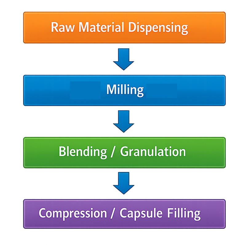
Because particle size distribution directly affects both product quality and process consistency, milling systems must be carefully designed, controlled, and qualified to ensure stable and reproducible operation. The following illustration shows the typical position of milling within the solid dosage manufacturing process, located between raw material dispensing and downstream unit operations such as blending, granulation, and compression.
1. Equipment Types
Several types of milling equipment are commonly used in pharmaceutical manufacturing. Selection of a milling system depends on the physical characteristics of the material, required particle size reduction, and the specific stage of the manufacturing process.
1.1 Hammer Mills
Hammer mills are commonly used for coarse size reduction and deagglomeration of dry materials. Their relatively simple mechanical design and high throughput capacity make them suitable for processing large quantities of pharmaceutical powders and granules. The illustration below shows a typical pharmaceutical hammer mill.
Hammer mills reduce particle size through repeated impact of high-speed rotating hammers mounted on a rotor. As material enters the milling chamber, particles collide with the rotating hammers and the internal surfaces of the chamber, causing them to fracture into smaller fragments.
A screen installed within the mill controls the maximum particle size of the discharged material. Particles remain inside the milling chamber until they are small enough to pass through the screen openings. The final particle size distribution is primarily determined by screen size, rotor speed, and feed rate.
1.2 Cone Mills
Cone mills, also known as conical screen mills, are widely used in pharmaceutical manufacturing for gentle particle size reduction and powder conditioning. These mills use a rotating impeller that forces material through a conical screen. As particles pass through the screen openings, size reduction occurs primarily through shear and mild impact forces.
Cone mills are commonly used for deagglomeration of powders, conditioning of granules after drying, and particle size control prior to blending or compression. Because the milling action is relatively gentle, these systems generate less heat and mechanical stress than hammer mills.
The illustration below shows a typical pharmaceutical cone mill. The equipment typically includes a feed hopper, conical milling chamber containing the rotating impeller and screen, and a discharge outlet where conditioned powder exits the system.
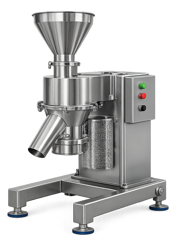
The controlled milling action and relatively low energy input make cone mills suitable for processing materials that are sensitive to heat, mechanical stress, or excessive particle size reduction.
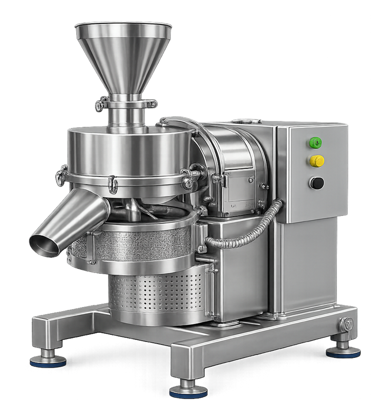
1.3 Comminuting Mills
Comminuting mills are high-speed impact mills used to achieve finer particle size reduction than standard cone mills. These systems employ rapidly rotating blades or pins that fracture particles through a combination of impact and shear forces.
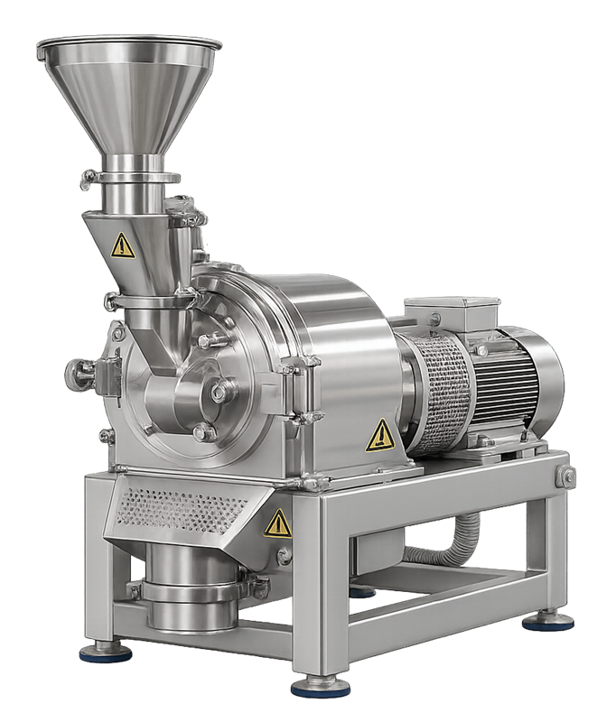
The illustration below shows a typical pharmaceutical comminuting mill. The equipment typically includes a feed hopper, enclosed milling chamber containing the high-speed rotor assembly, and a discharge section where milled powder exits after passing through the installed screen.
Because these mills operate with higher mechanical energy than cone mills, operating conditions must be carefully controlled to prevent excessive heat generation or degradation of temperature-sensitive materials.
1.4 Screening Mills
Screening mills are used primarily for powder conditioning rather than aggressive particle size reduction. Their main function is to remove agglomerates and produce a more uniform particle size distribution before materials enter downstream processing equipment.
These systems typically use rotating paddles or impellers that gently force powder through a screen. This action breaks soft agglomerates and ensures that granules passing through the system meet the required size range while minimizing mechanical stress on the material.
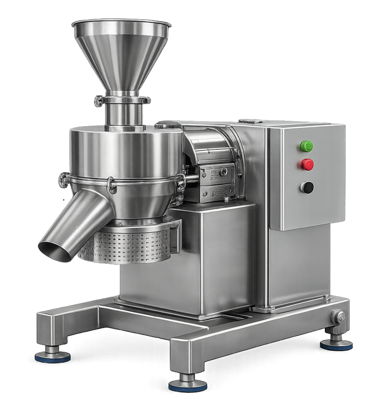
The illustration below shows a typical pharmaceutical screening mill. Such equipment is commonly installed upstream of blending, granulation, or compression operations to ensure consistent powder flow behavior and reliable downstream processing.
2. Design Considerations
Milling equipment used in pharmaceutical manufacturing must be designed to provide controlled particle size reduction while maintaining hygienic conditions and preventing contamination.
2.1 Particle Size Control
The primary objective of milling equipment is to produce a controlled and consistent particle size distribution suitable for downstream processing. Particle size is typically regulated through selection of screen size, rotor speed, and feed rate. These operating parameters must be carefully defined to achieve the required particle size while avoiding excessive generation of fines that may negatively affect powder flow, blending behavior, or tablet compression performance.
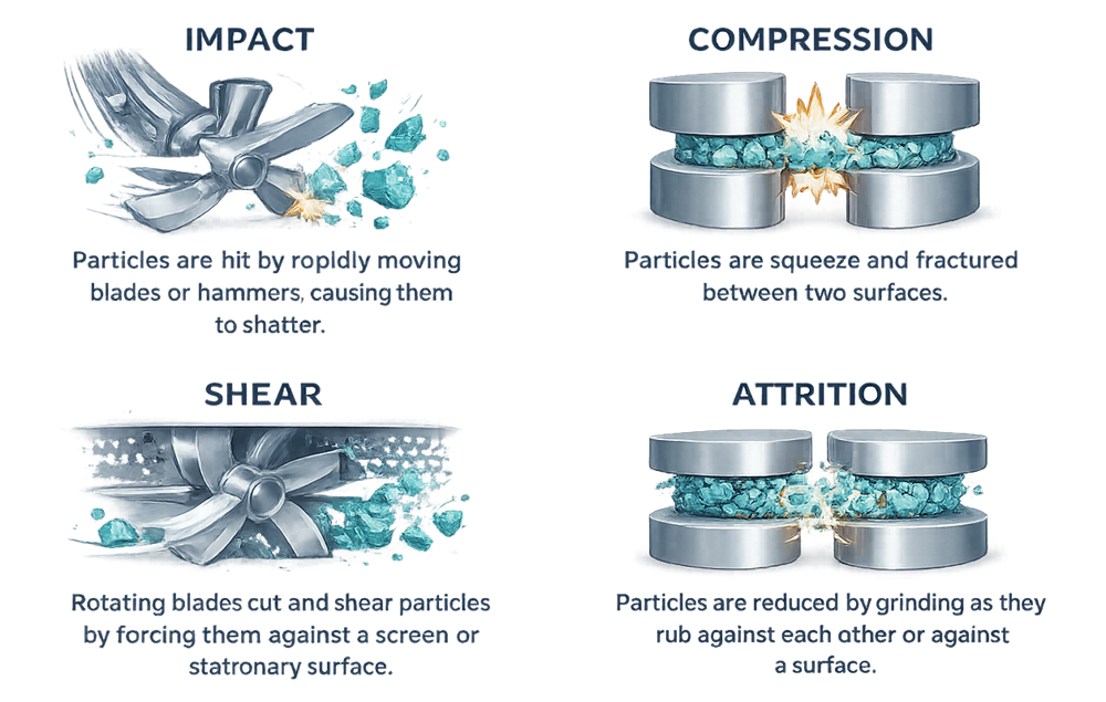
Particle size reduction occurs through several mechanical mechanisms depending on the design of the milling system. These mechanisms include impact, compression, shear, and attrition. Different mill types rely on these forces to varying degrees to fracture particles and reduce their size.
The illustration below demonstrates the principal particle size reduction mechanisms used in pharmaceutical milling equipment. Impact occurs when particles collide with rapidly moving components such as hammers or blades. Compression fractures particles between two surfaces. Shear forces cut or tear particles as they pass through narrow gaps or across screens. Attrition reduces particle size through friction as particles rub against each other or against internal mill surfaces. Understanding these mechanisms helps determine the most appropriate milling technology for a given material and process requirement.
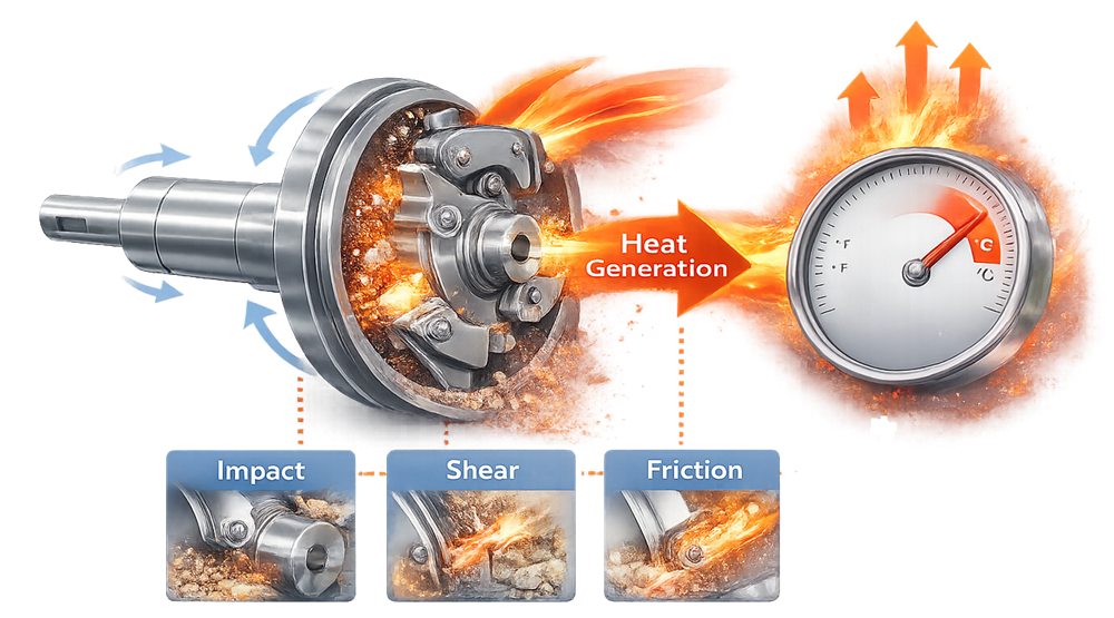
2.2 Heat Generation
Mechanical energy applied during milling is partially converted into heat as particles fracture and interact with rotating components and internal mill surfaces. Impact, shear, and friction within the milling chamber can raise the temperature of the processed material. The level of heat generated depends on operating parameters such as rotor speed, feed rate, residence time, and the mechanical properties of the powder.
Excessive temperature rise may affect heat-sensitive active pharmaceutical ingredients or excipients. Elevated temperatures can cause chemical degradation, changes in crystallinity, loss of volatile components, or altered powder flow behavior, potentially impacting downstream processing and product quality.
For this reason, milling systems and operating conditions must be selected to limit unnecessary heat generation. Control of rotor speed, feed rate, and residence time, together with equipment designs that allow efficient heat dissipation, helps ensure that particle size reduction is achieved without compromising material stability.
2.3 Dust Containment
Particle size reduction often generates airborne powder due to the mechanical forces applied during milling. Impact and friction within the milling chamber can release fine particles that become suspended in the surrounding air. If not properly controlled, these airborne particles may contaminate the manufacturing environment, expose operators to pharmaceutical dust, or lead to cross-contamination between products.
For this reason, milling equipment is typically integrated with dust collection systems or contained transfer devices that maintain negative pressure within the milling chamber. Dust extraction systems capture airborne particles generated during milling and direct them to filtration units, preventing powder release into surrounding areas. Proper containment design ensures that milling operations remain controlled while maintaining product quality and operator safety.
2.4 Cleanability and Sanitary Design
All product-contact surfaces must be constructed from materials compatible with pharmaceutical cleaning procedures. Stainless steel surfaces, smooth internal geometries, and minimal crevices are required to allow effective removal of product residues between batches.
Equipment design must minimize areas where powder can accumulate and should allow convenient access for inspection and cleaning. Components such as screens, rotors, and internal milling chambers should be easily removable or accessible to ensure thorough cleaning and verification of residue removal.
3. Utility and Infrastructure Interfaces
Milling equipment operates as part of a broader manufacturing system and therefore depends on several facility utilities and supporting infrastructure components.
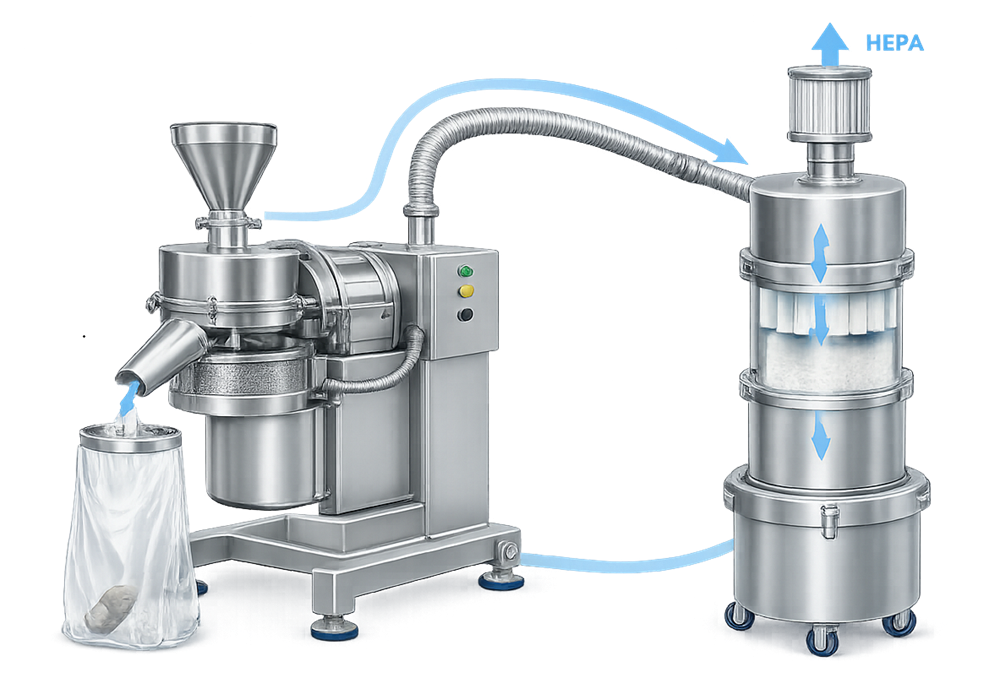
Dust Collection Systems
Particle size reduction frequently generates fine airborne powder. Milling systems are therefore commonly connected to dust collection units that maintain negative pressure within the milling chamber. These systems capture airborne particles through ducting and filtration equipment, preventing powder release into the surrounding environment and reducing the risk of cross-contamination.
The illustration below shows a typical milling system integrated with a dust collection unit. The diagram demonstrates how airborne powder generated during milling is captured through ducting and directed to a filtration system, maintaining containment and preventing release of fine particles into the manufacturing environment. size reduction frequently generates airborne powder. Milling equipment is therefore typically connected to dust collection systems that maintain negative pressure within the milling chamber and capture airborne particles generated during milling operations.
Electrical Power and Grounding
Electrical power supplies drive the mill rotor, motors, and control systems that regulate operating parameters such as speed and feed rate. Proper electrical grounding is essential when handling combustible powders to prevent electrostatic discharge that could ignite suspended dust.
Compressed Air Systems
Compressed air may support pneumatic conveying systems used to feed raw materials into the mill or to transport milled powder to downstream equipment. Air quality must be controlled to ensure that contaminants such as oil, moisture, or particulates do not enter the product stream.
Facility Layout and Material Flow
Facility design must support controlled material movement into and out of milling operations. Milling systems are often integrated with contained transfer devices that connect upstream dispensing equipment with downstream blending, granulation, or compression processes.
4. Qualification Considerations
Qualification of milling equipment demonstrates that the system is properly installed, functions as intended across its operating range, and consistently produces the required particle size distribution for downstream processing. Because milling directly influences powder flow behavior, blend uniformity, and dissolution characteristics, qualification must verify both mechanical performance and process-related outcomes.
The qualification program typically includes installation verification, operational performance testing, particle size evaluation, containment assessment, and verification of cleaning capability.
4.1 Installation Qualification
Installation Qualification confirms that the milling equipment has been installed according to approved engineering drawings, manufacturer specifications, and facility design requirements.
- Verification activities typically include confirmation of equipment identification such as manufacturer, model number, and serial number. Materials of construction for all product-contact surfaces must be verified to ensure compatibility with pharmaceutical cleaning procedures and regulatory expectations.
- Utility connections must also be confirmed during installation qualification. These may include electrical power supply, grounding systems for electrostatic discharge protection, dust collection connections, and compressed air interfaces if the mill is integrated with pneumatic transfer systems.
- Mechanical installation must be inspected to confirm proper mounting, alignment, and accessibility for operation, cleaning, and maintenance. The installation of key components such as rotors, impellers, screens, and safety guards must also be verified against design specifications.
- Safety features including emergency stop systems, access interlocks, and mechanical guards must be tested to confirm correct installation and functionality.
- Documentation generated during installation qualification establishes the baseline configuration of the milling system.
4.2 Operational Qualification
Operational Qualification demonstrates that the milling system operates correctly across its intended operating range. Testing during this phase evaluates Operational Qualification demonstrates that the milling system operates correctly across its intended operating range. Testing during this phase evaluates both the mechanical performance of the mill and the functionality of associated control systems.
Typical OQ testing activities include:
- Verification of rotor speed ranges to confirm that the mill can operate at the specified rotational speeds required for particle size reduction
- Evaluation of feed rate capability to ensure that the system can process material at defined throughput rates without excessive vibration or mechanical instability
- Verification of screen installation, fastening mechanisms, and the ability to operate with different screen sizes where applicable
- Functional testing of control systems, alarms, safety interlocks, and start–stop controls
- Verification that safety interlocks prevent mill operation when access doors or guards are open
- Confirmation of correct coordination between the mill and any upstream or downstream material transfer systems
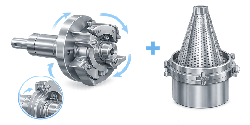
Screens and rotor assemblies are critical components that determine the final particle size distribution produced by the mill. Proper installation, inspection, and verification of these components are essential to maintain consistent milling performance. The illustration below shows a typical rotor and screen assembly used in pharmaceutical milling equipment.
4.3 Particle Size Verification
One of the most important aspects of milling equipment qualification is confirmation that the mill consistently produces powders within the required particle size distribution.
- During operational testing, representative material samples are milled under defined operating conditions. The resulting powder is then analyzed using particle size measurement methods such as sieve analysis or laser diffraction.
- These tests confirm that the selected rotor speed, screen size, and feed rate combination produces material within the target particle size range required for the manufacturing process.
- Particle size verification may also evaluate variability across multiple runs to ensure consistent milling performance.
4.4 Containment and Dust Control Verification
Milling operations frequently generate airborne dust due to the mechanical forces applied during particle size reduction. Containment verification ensures that dust collection and containment systems effectively control airborne particles during milling operations.
- Testing may include confirmation of airflow rates within connected dust collection systems, verification of negative pressure within the milling chamber, and inspection of filter integrity.
- Smoke visualization or particulate monitoring may also be performed to confirm that airborne powder is captured by the dust extraction system rather than released into the surrounding manufacturing environment.
- Effective containment is essential for both product protection and operator safety.
4.5 Cleaning Verification
Milling equipment must support effective removal of product residues between batches to prevent cross-contamination. Cleaning verification confirms that residues can be removed from milling chambers, screens, rotors, and internal surfaces using approved cleaning procedures.
- Verification activities typically include visual inspection of cleaned equipment and, where required, analytical residue testing to confirm that cleaning procedures effectively remove product residues.
- Particular attention must be given to areas where powder accumulation may occur, including screen surfaces, rotor blades, internal corners of the milling chamber, and discharge ports.
- Equipment design should allow convenient disassembly or access to these areas for inspection and cleaning.
Comprehensive qualification of milling equipment ensures that particle size reduction is performed in a controlled and reproducible manner, supporting consistent powder properties and reliable downstream processing in pharmaceutical manufacturing.
5. Common Risk Points
Milling operations introduce several potential risks that must be carefully controlled through equipment design, operating procedures, and routine monitoring. Because milling directly influences particle size distribution, any instability or deviation in milling conditions can affect downstream processing steps such as blending, granulation, compression, and dissolution performance of the finished dosage form.
Understanding these risks is important when selecting milling equipment, defining operating parameters, and establishing qualification and maintenance programs.
5.1 Excessive Particle Size Reduction
One of the most common risks during milling is excessive particle size reduction resulting from high rotor speeds, aggressive milling conditions, or improper screen selection. When particles are milled too aggressively, the process may generate a large proportion of very fine particles.
Excessive fines can negatively affect powder flowability, leading to poor feeding performance during blending or tablet compression. Fine particles also increase the risk of powder segregation because smaller particles may migrate differently than larger particles during handling and transfer. In addition, increased surface area associated with very fine particles may affect dissolution characteristics or chemical stability of active pharmaceutical ingredients. Control of milling energy through proper selection of rotor speed, screen size, and feed rate is therefore essential to maintain the desired particle size distribution.
5.2 Thermal Degradation of Materials
Milling introduces mechanical energy into the powder bed through impact, shear, and friction. A portion of this energy is converted into heat within the milling chamber as particles interact with rotating components and internal mill surfaces.
If excessive heat is generated, temperature-sensitive materials may degrade. Certain active pharmaceutical ingredients, polymers, or excipients may soften, melt, or undergo chemical degradation when exposed to elevated temperatures. Thermal buildup may also cause powders to agglomerate or adhere to internal mill surfaces, reducing milling efficiency and complicating cleaning.
Equipment design must therefore allow effective heat dissipation, and operating parameters such as rotor speed, feed rate, and residence time should be selected to limit thermal stress on the processed material. The illustration below demonstrates how mechanical forces during milling can generate heat within the milling chamber and increase powder temperature.
5.3 Screen Damage or Improper Installation
Screens play a critical role in controlling the final particle size distribution produced by the mill. Damaged screens, worn perforations, or improperly installed screen assemblies can allow oversized particles to pass through the milling system.
This may result in inconsistent particle size distribution entering downstream processing steps, potentially affecting blending efficiency or tablet compression performance. Improperly secured screens may also shift during operation, creating mechanical instability or abnormal vibration within the milling chamber. Routine inspection of screens and verification of correct installation during equipment setup are therefore important preventive controls.
5.4 Powder Accumulation and Residue Hold-Up
Powder accumulation within the milling chamber or associated transfer components represents another significant risk. Residual material may collect in corners, behind screens, around rotor assemblies, or within discharge chutes.
If this retained material is not fully removed during cleaning, it may contaminate subsequent batches. Residual powders may also degrade over time or become compacted, making them more difficult to remove. Equipment design should minimize dead zones and allow easy access to internal surfaces for inspection and cleaning. Proper cleaning procedures and inspection protocols must be established to verify complete removal of residues between batches.
5.5 Variable Feed Rates
Consistent feeding of material into the milling chamber is important for maintaining stable milling performance. If feed rates fluctuate significantly, the mill may operate outside its optimal processing conditions.
Low feed rates may result in excessive milling energy being applied to the powder, producing excessive fines. Conversely, very high feed rates may overload the milling chamber, reducing milling efficiency and producing particles larger than the desired size range. Feed rate variability may also cause fluctuations in motor load, vibration, or process temperature, further affecting milling performance. Controlled feeding systems, including screw feeders or metered transfer systems, are often used to maintain stable feed conditions.
5.6 Dust Generation and Powder Loss
Milling operations frequently generate airborne dust due to the mechanical impact and fracture of particles. If containment systems are inadequate, airborne powder may escape into surrounding manufacturing areas.
Dust release may create both contamination risks and occupational exposure concerns for operators. In addition, uncontrolled powder loss may lead to discrepancies in material balances during batch manufacturing. Effective integration of milling equipment with dust collection systems and contained transfer devices is therefore essential to maintain environmental control and product accountability.
Effective equipment design, appropriate operating controls, and routine inspection of milling components are essential to minimize these risks and ensure consistent particle size reduction performance in pharmaceutical manufacturing.