
Single-Use Systems in Fill-Finish
Single-use systems in fill-finish operations replace stainless steel product-contact assemblies with pre-sterilized, disposable fluid paths. In ISO 5 critical processing environments, these assemblies become part of the sterile boundary and directly influence sterility assurance, product quality, and regulatory compliance. While elimination of CIP and SIP reduces cleaning validation burden, risk shifts toward material compatibility, irradiation control, mechanical reliability, and supplier lifecycle oversight. Disposable technology simplifies certain controls but introduces different validation expectations.
This article addresses single-use assemblies used in formulation hold, sterile filtration, product transfer, pooling, and aseptic filling. Upstream bioprocessing systems are excluded unless directly integrated with fill-finish operations.
1. System Architecture and Closed Processing Strategy
Single-use fill-finish assemblies typically include sterile bags, tubing manifolds, disposable filters, aseptic connectors, sterile disconnects, pump tubing, and filling needles. These are supplied pre-assembled or partially assembled and terminally sterilized by irradiation. The diagram below illustrates a typical closed single-use fluid pathway within an ISO 5 filling environment.
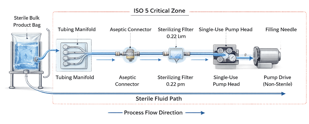
The objective is to create a functionally closed system from bulk sterile product to the filling needle without exposure to the surrounding environment.
Closed processing requires:
• Sterile connectors or validated tube welding
• Controlled staged de-bagging procedures
• No open manipulations within ISO 5
• Documented sterile boundary definition
A system cannot be classified as closed based solely on disposable status. Closure integrity must be technically justified and procedurally controlled.
2. Sterility Assurance and Irradiation Control
Most single-use assemblies are sterilized using gamma irradiation validated under ISO 11137. Suppliers establish the sterilization dose to achieve an SAL of 10⁻⁶ and provide Certificates of Irradiation.
Regulatory accountability remains with the drug manufacturer.
Under 21 CFR 211.113 and 211.94, the user must ensure that product-contact components are sterile and suitable for intended use. Supplier certification does not replace internal oversight. User control measures include:
• Supplier qualification and audit
• Review of sterilization validation documentation
• Verification of dose range and bioburden assumptions
• Incoming inspection of packaging integrity
• Storage condition control
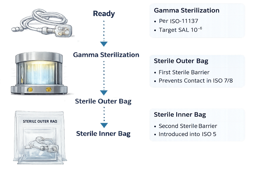
In the Supplier Sterilization and Packaging Flow diagram, the sequence illustrates two separate control concepts: sterilization assurance and environmental transition control.
After a single validated gamma sterilization step per ISO 11137, the assembly is enclosed in a double-bag configuration. These two layers serve different purposes during movement through classified areas.
The outer bag is a transport barrier. It protects the sterile inner package during shipping and handling and may be exposed to ISO 8 or warehouse environments. It must be removed in a lower-grade area, typically ISO 8 or ISO 7, before transfer toward the critical zone. The inner bag is the validated sterile barrier. It remains intact during transfer into ISO 7 and is only opened under ISO 5 unidirectional airflow. This preserves sterility until point of use.
Staged packaging removal supports the cleanroom contamination gradient. Removing the outer layer outside ISO 5 prevents particulate and microbial burden from being introduced into the critical zone. The diagram should therefore be interpreted as a contamination control pathway, not just a sterilization sequence.
Improper handling invalidates irradiation assurance.
3. Extractables and Leachables Evaluation
Polymeric materials used in single-use systems include polyethylene, EVA, polypropylene, silicone, and thermoplastic elastomers. These materials may release chemical species under stress conditions. Risk evaluation must address:
• Product formulation chemistry
• Contact duration and temperature
• Surface area-to-volume ratio
• pH extremes
• Presence of solvents or surfactants
Guidance from USP <665> and USP <1665> supports structured assessment.
The model below illustrates a structured extractables risk assessment framework linking polymer composition, process exposure variables, analytical data, and toxicological evaluation to a documented risk acceptance decision.
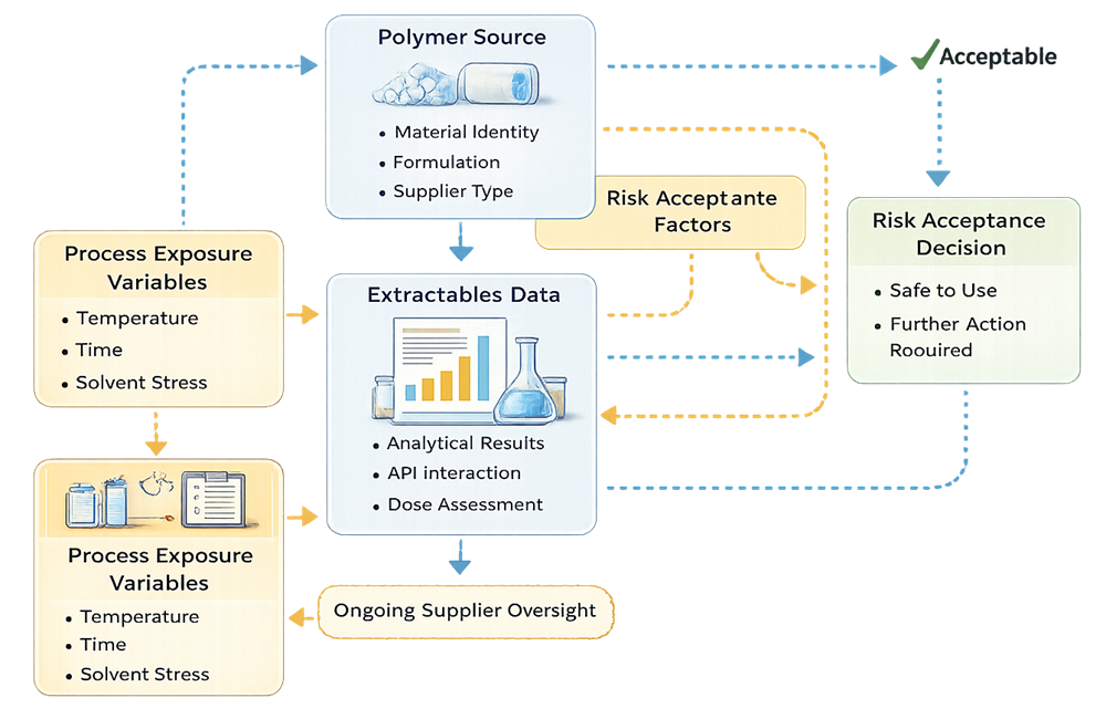
Supplier extractables data provides baseline information but does not eliminate the need for product-specific compatibility review. Toxicological assessment must be documented and traceable. Worst-case simulation may be required for:
• Extended hold time
• Elevated temperature exposure
• Maximum solvent strength
Extractables risk is formulation-dependent and cannot be generalized across products.
4. Mechanical Integrity and Operational Limits
Disposable assemblies introduce mechanical failure modes not present in fixed stainless systems. Potential risks include:
• Tubing rupture under peristaltic pump stress
• Bag seam failure at high fill volumes
• Connector misalignment
• Pinholes from handling damage
• Filter housing cracking under pressure spikes
Mechanical failure modes unique to disposable assemblies must be identified and controlled.

Maximum allowable operating pressure and flow rate must be defined during qualification. Tubing durometer must be compatible with pump specifications. Pre-use verification controls may include:
• Visual inspection under illumination
• Pressure hold testing
• Filter integrity testing pre- and post-use
• Confirmation of connector locking mechanisms
Mechanical qualification is a sterility control measure, not a cosmetic check.
5. Qualification Strategy
Single-use systems used in fill-finish operations require a structured, risk-based lifecycle qualification approach. Although these assemblies are disposable, they form part of the critical sterile boundary and must be qualified with the same rigor applied to permanent equipment.
Qualification depth must be aligned with product risk, route of administration, formulation characteristics, and process duration. The absence of CIP and SIP does not reduce validation scope; it shifts focus toward materials, configuration control, and operational robustness.
5.1 Design Qualification
Design Qualification establishes documented evidence that the selected single-use system is suitable for its intended use before implementation.
DQ must be product- and process-specific. Generic approval of a supplier platform is insufficient. Key DQ elements include:
Material Suitability
• Identification of all product-contact materials
• Confirmation of polymer type, additives, and stabilizers
• Review of supplier material specifications and certificates
• Assessment of compatibility with formulation pH, solvent content, and surfactants
Extractables and Leachables Risk Assessment
• Review of supplier extractables data under exaggerated conditions
• Comparison to intended process parameters
• Toxicological assessment of potential leachables
• Justification of worst-case surface area-to-volume ratio
Reference to USP <665> and USP <1665> should be documented where applicable.
Sterilization Method and Dose Range
• Confirmation of irradiation method under ISO 11137
• Review of validated dose range and SAL 10⁻⁶ justification
• Evaluation of maximum dose impact on material mechanical properties
• Assessment of bioburden control strategy at supplier
Mechanical and Pressure Design Limits
• Maximum allowable working pressure
• Burst pressure rating
• Tubing wall thickness and durometer
• Compatibility with selected pump system
Supplier Quality System Review
• Audit status and quality agreement
• Change notification process
• Traceability controls
• Batch release documentation review
Worst-case parameters must be defined before approval, including maximum hold time, maximum flow rate, highest product viscosity, and longest filling duration.
DQ approval establishes the validated design envelope.
5.2 Installation Verification
Because single-use assemblies are replaced each batch or campaign, traditional fixed-equipment IQ is not applicable. However, documented installation verification remains mandatory.
Installation verification confirms that the system used in production matches the approved design configuration.
Required controls include:
Configuration Verification
• Verification against controlled assembly diagram
• Confirmation of correct part numbers and lot numbers
• Inspection of tubing lengths and connector orientation
Routing Accuracy
• Verification that tubing paths avoid kinks or excessive bend radius
• Confirmation of correct pump head installation
• Verification that vent filters and pressure relief paths are correctly installed
Labeling and Traceability
• Recording of assembly lot number in batch documentation
• Verification of irradiation status and expiration date
• Confirmation of sterile barrier integrity prior to de-bagging
Sterile Boundary Integrity
• Inspection of inner sterile packaging prior to ISO 5 introduction
• Verification of proper staged de-bagging procedure
Incorrect configuration or routing may compromise sterility or create pressure instability. Installation verification must be documented per batch or per campaign, depending on risk.
5.3 Operational Qualification
Operational Qualification establishes and documents the validated operating limits of the single-use system under simulated or controlled process conditions.
OQ must challenge worst-case mechanical and functional conditions within the approved design envelope. Parameters to be qualified include:
Flow Rate Range
• Minimum and maximum validated flow
• Impact of viscosity variation
• Stability of pump performance over time
Pump Speed Limits
• Maximum RPM without tubing fatigue
• Confirmation of flow accuracy at target fill volumes
• Evaluation of pulsation impact on system integrity
Pressure Limits
• Maximum differential pressure across filters
• System response to transient pressure spikes
• Verification of leak-free operation at upper pressure limit
Sterile Connection Procedures
• Qualification of aseptic connector engagement
• Operator reproducibility study
• Verification that connection procedure does not breach sterile boundary
Maximum Hold Time
• Validation of product contact duration prior to fill
• Evaluation of potential material interaction over hold period
Simulated runs using surrogate fluids are acceptable when justified and when they adequately represent viscosity and flow behavior. Filter integrity testing must be performed before and after qualification runs where applicable.
OQ establishes documented operating limits that become part of batch manufacturing controls.
5.4 Performance Qualification
Performance Qualification confirms that the single-use system performs as intended under routine commercial conditions using actual product or validated simulation.
PQ must demonstrate:
• Stable operation during full-duration filling
• Absence of leaks or mechanical failures
• Maintenance of validated pressure and flow ranges
• Integrity of sterile boundary throughout operation
Worst-case conditions should include:
• Maximum batch volume
• Longest fill duration
• Highest viscosity product
• Maximum number of sterile connections
If the single-use assembly forms part of the aseptic pathway, media fill must incorporate the full commercial configuration. Media simulation must challenge all sterile connection points and maximum process duration.
Configuration changes between campaigns require documented impact assessment. Depending on risk, actions may include partial requalification, targeted testing, or repetition of media simulation.
PQ confirms that the validated design envelope performs reliably in real production conditions and maintains sterility assurance throughout the fill-finish operation.
6. Integration with Aseptic Process Simulation
Single-use components that define the sterile pathway must be included in process simulation. Media fill studies must challenge:
• All sterile connections
• Maximum filling duration
• Extended hold times
• Worst-case container configuration
Simulation configuration must reflect routine commercial practice. Deviations require formal risk assessment.
7. Change Control and Supplier Lifecycle Oversight
Single-use technology introduces supplier-dependent risks. Potential change triggers include:
• Polymer formulation modification
• Tubing material substitution
• Irradiation facility change
• Packaging redesign
• Connector geometry revision
Formal change notification agreements are required. Each change must undergo documented impact evaluation, potentially resulting in:
• Documentation update
• Targeted testing
• Partial requalification
• Full PQ or media fill repetition
Periodic review should trend:
• Leak events
• Connector failures
• Deviation frequency
• Supplier performance metrics
Disposable systems require continuous lifecycle control, not one-time approval.
8. Regulatory Expectations
Applicable regulatory frameworks include:
• 21 CFR 211.65 – Equipment construction
• 21 CFR 211.94 – Containers and closures
• 21 CFR 211.113 – Microbiological contamination control
• EU GMP Annex 1 – Closed system expectations
• ISO 11137 – Sterilization validation
Regulators expect documented risk assessment, supplier oversight, and science-based justification. Elimination of cleaning validation does not eliminate validation responsibility.
Conclusion
Single-use systems in fill-finish reduce cleaning complexity and cross-contamination risk but introduce material science, irradiation control, mechanical integrity, and supplier governance risks. Effective control requires:
• Structured qualification
• Defined operating limits
• Configuration management
• Supplier lifecycle oversight
• Integration into aseptic simulation
Disposable status does not reduce regulatory scrutiny. It changes the validation focus.