
Sterile Filter Integrity and Lifecycle Control
1. Purpose and Scope
Sterile filtration is a critical sterility assurance control in aseptic processing. The sterilizing-grade filter is frequently the final microbial barrier prior to filling or sterile hold. Integrity testing confirms that this barrier remains intact before and after product exposure.
This article defines a comprehensive lifecycle control framework for sterile filters and their associated integrity testing systems. Scope includes:
• Filter selection and bacterial retention validation
• Integrity test method correlation
• Qualification of integrity testing equipment
• Routine pre-use and post-use testing
• Trending and lifecycle monitoring
• Change control and requalification
• Failure investigation and data integrity control
Sterility assurance depends equally on membrane performance and the validated capability of the integrity testing system.
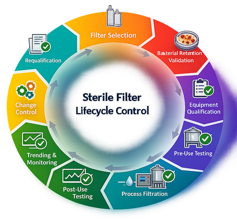
Sterile filter integrity testing is not an isolated verification step. It operates within a defined lifecycle that links filter selection, bacterial retention validation, equipment qualification, routine integrity testing, trending, change control, and requalification. The following model illustrates the closed-loop control structure required to maintain sterility assurance over the operational life of the filtration system.
2. Sterilizing-Grade Filters: Technical Foundation
Sterilizing-grade membrane filters, typically 0.22 µm rated, are validated to retain challenge organisms such as Brevundimonas diminuta under defined worst-case conditions. Common membrane materials include:
• Polyethersulfone
• Polyvinylidene fluoride
• Nylon
• Regenerated cellulose
Selection must consider:
• Product compatibility
• Adsorption characteristics
• Extractables and leachables
• Pressure and temperature limits
• Maximum throughput and exposure duration
Filter selection is part of process validation and must be supported by vendor certification and internal technical assessment.
3. Regulatory Expectations
Regulatory authorities consider sterilizing filtration a high-risk unit operation. Expectations are defined in:
• 21 CFR 211.113 and 211.160
• EU GMP Annex 1
• PDA Technical Reports
• USP sterilization guidance
• ICH Q9 risk management principles
Authorities require documented evidence that:
• Bacterial retention is validated
• Integrity test limits correlate to retention validation
• Integrity testing is performed before and after use
• Failures are investigated
• Data integrity controls are implemented
Integrity testing is not proof of sterility. It is an indirect but validated assurance tool linked to bacterial retention studies.
4. Bacterial Retention Validation
Before routine use, filters must undergo microbial challenge studies under worst-case conditions. Validation defines:
• Minimum acceptable bubble point
• Maximum diffusion or forward flow
• Acceptable pressure decay limits
• Worst-case pressure and temperature
• Maximum process duration
Integrity test acceptance criteria must be directly traceable to retention validation data. Arbitrary vendor limits without validation traceability are not acceptable.
5. Integrity Testing Methods
Integrity testing verifies membrane integrity through controlled gas pressurization and measurement of gas flow behavior across a wetted or dry membrane. Each method is based on defined physical principles and must correlate to validated bacterial retention performance.
5.1 Bubble Point Testing
Principle
Bubble point testing determines the minimum pressure required to displace liquid from the largest pores of a fully wetted membrane. When applied gas pressure exceeds capillary forces holding the liquid within the pore structure, continuous gas flow occurs. The theoretical relationship is defined by the capillary flow equation, where bubble point pressure is inversely proportional to maximum pore diameter. Operational Characteristics
• Requires complete and uniform wetting
• Sensitive to membrane hydrophilicity
• Typically performed using air or nitrogen
• Produces a discrete pressure value
Application
Bubble point testing is commonly used for hydrophilic sterilizing-grade filters. It is particularly useful for confirming maximum pore size integrity after sterilization.
Limitations
• Sensitive to incomplete wetting
• Less sensitive than diffusion testing for detecting small defects
• May be influenced by temperature variation
Acceptance limits must be derived from retention validation and manufacturer qualification data.
5.2 Diffusion or Forward Flow Testing
Principle
Diffusion testing measures the rate of gas diffusion through a wetted membrane at a pressure below the bubble point. Gas dissolves into the wetting fluid within the pores and diffuses through the membrane according to Fick’s law. Forward flow is proportional to membrane area, temperature, and applied pressure.
Operational Characteristics
• Performed below bubble point pressure
• Generates a quantitative gas flow rate
• Highly sensitive to small defects
• Widely automated in modern integrity testers
Application
Diffusion testing is the most common routine integrity test for sterilizing-grade liquid filters due to its sensitivity and repeatability.
Limitations
• Influenced by temperature
• Requires stabilization time
• Sensitive to hose volume and test configuration
Acceptance limits must account for filter size and membrane surface area.
5.3 Pressure Hold (Pressure Decay) Testing
Principle
Pressure hold testing measures the rate of pressure decay in a closed, pressurized system over time. Any loss of pressure reflects gas diffusion or leakage through the membrane or system.
Operational Characteristics
• Simpler instrumentation requirements
• Measures pressure loss rather than direct flow
• Suitable for small systems or when flow sensors are not available
Application
Often used for smaller filter assemblies or as a secondary verification method.
Limitations
• Less sensitive than direct diffusion measurement
• More susceptible to system leaks unrelated to membrane integrity
• Strongly influenced by system volume
System tightness must be verified before interpreting results.
5.4 Water Intrusion Testing
Principle
Water intrusion testing is primarily used for hydrophobic membrane filters such as gas sterilizing filters. Instead of wetting the membrane with alcohol or water, purified water is applied under pressure. The amount of water that penetrates into the hydrophobic structure under defined pressure is measured.
Operational Characteristics
• Designed for hydrophobic membranes
• Eliminates need for solvent wetting
• Measures water penetration volume over time
Application
Common for sterilizing-grade gas filters used in venting applications.
Limitations
• Requires precise pressure control
• Temperature dependent
• Acceptance limits must be strictly defined
5.5 Method Selection and Validation
Integrity test method selection must consider:
• Membrane material and hydrophilicity
• Application type (liquid or gas filtration)
• Filter surface area
• Process temperature
• Instrument capability
Method selection and acceptance criteria must be validated during equipment qualification and directly correlated to bacterial retention studies. The chosen test must demonstrate:
• Adequate sensitivity to detect membrane defects
• Repeatability and reproducibility
• Robustness under routine manufacturing conditions
Integrity testing is valid only when physical principles, instrument capability, and validation data are aligned.
6. Integrity Testing Equipment and System Qualification
Integrity testing equipment is GMP-critical. The tester determines whether a batch is released or rejected. Measurement capability must therefore be qualified and controlled.
The photograph below shows a commercially available automated filter integrity tester used in GMP sterile filtration applications. Such systems perform diffusion, bubble point, and pressure decay testing with validated pressure control, automated calculation, and secure electronic data handling.
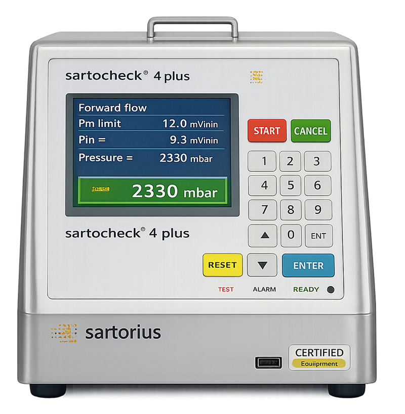
Equipment configurations may include:
• Portable automated integrity testers
• Skid-integrated test modules
• Centralized automated test systems
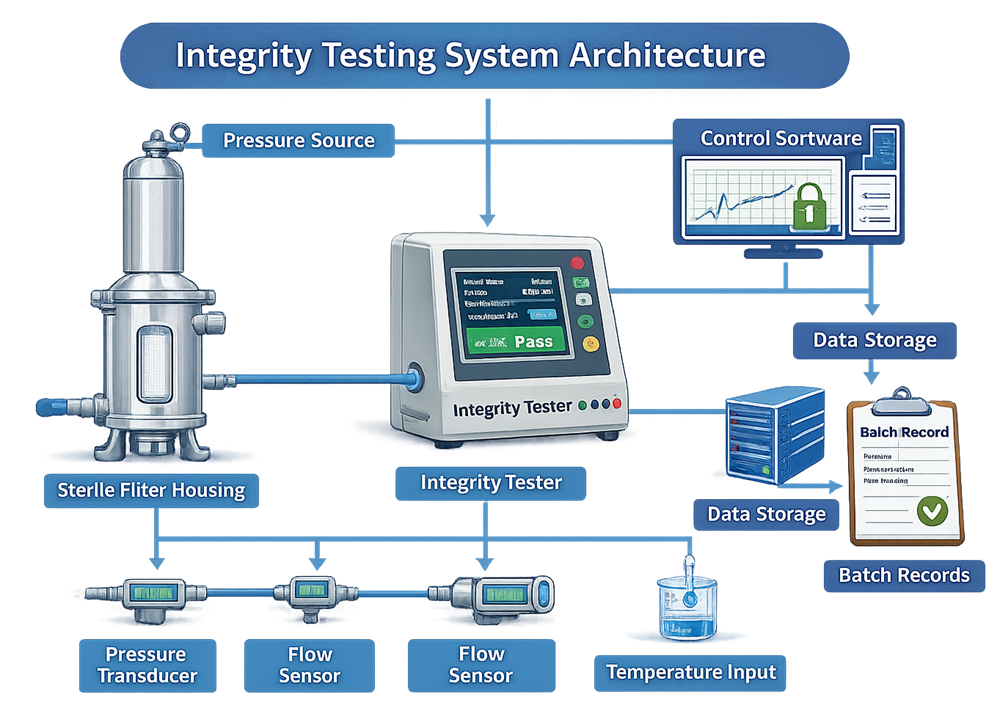
The system typically includes:
• Pressure transducers
• Flow sensors
• Temperature compensation algorithms
• Control software
Integrity testing depends on a validated measurement system composed of pressure regulation, sensing elements, control software, and data handling functions. The architecture diagram below illustrates the functional relationship between the filter housing, integrity tester, sensors, control logic, and batch record interface. This system-level view emphasizes that sterility decisions are based on controlled instrumentation, not on the membrane alone.
6.1 Equipment Qualification
Installation Qualification must verify:
• Correct installation and utilities
• Pressure regulator stability
• Sensor range suitability
• Software version documentation
Operational Qualification must verify:
• Pressure measurement accuracy
• Flow measurement precision
• Repeatability and reproducibility
• Alarm functionality
• Parameter lockout controls
• Interlock functionality if skid-integrated
Performance Qualification must demonstrate:
• Reliable operation under routine production configuration
• Stable test results across expected operating range
• Correct integration with batch documentation systems
Integrity testers cannot be treated as simple tools. They are measurement systems requiring full validation.
7. Calibration and Measurement Control
Critical components requiring calibration include:
• Pressure sensors
• Flow measurement devices
• Temperature sensors
Calibration tolerance must be significantly tighter than filter acceptance limits. Measurement uncertainty must not compromise sterility decisions.
Out-of-tolerance conditions require impact assessment on previously executed integrity tests and associated product batches.
8. Pre-Use and Post-Use Testing Strategy
A compliant sterile filtration process includes:
Pre-Use Post-Sterilization Integrity Testing
Confirms no damage occurred during installation or sterilization.
Post-Use Integrity Testing
Confirms filter integrity was maintained throughout product processing.
Failure of post-use testing invalidates sterility assurance unless investigation demonstrates a test artifact with documented scientific justification. Test execution must control:
• Wetting procedure
• Stabilization time
• Hose configuration
• Isolation valves
• Temperature equilibration
Improper setup frequently causes false failures and must be controlled by validated SOPs.
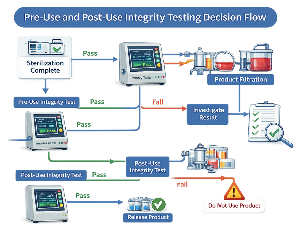
Sterility assurance decisions occur at defined control points before and after product filtration. The decision flow below illustrates how pre-use and post-use integrity testing integrates with sterilization, product processing, and batch release. It clarifies pass/fail pathways and investigation triggers to prevent uncontrolled product exposure.
9. Integration into Equipment Qualification Lifecycle
Sterile filters operate within housings or filtration skids. Qualification must include:
Installation verification of housings and seals
Pressure rating confirmation
Vent and drain configuration
Control logic for automated systems
Alarm and interlock verification
IQ, OQ, and PQ must evaluate the complete system, not only the membrane cartridge.
10. Routine Monitoring and Trending
Lifecycle control requires trending of:
• Forward flow values
• Bubble point results
• Differential pressure during process
• Total throughput
• Use duration
Gradual upward diffusion trends may indicate fouling or membrane degradation. Trending supports proactive risk mitigation and controlled replacement intervals. Maximum allowable throughput and service life must be documented and justified.
11. Change Control and Requalification
Requalification may be required due to:
• Filter manufacturer change
• Membrane type change
• Housing modification
• Sterilization cycle modification
• Process fluid change
• Repeated integrity deviations
Impact assessment must evaluate need for:
• Additional retention validation
• Partial OQ
• Full requalification
All changes require formal change control and documented risk assessment.
12. Failure Investigation and Risk Assessment
Integrity test failures require structured investigation including:
• Verification of test configuration
• Review of instrument calibration
• Review of sterilization cycle data
• Review of process pressure history
• Evaluation of operator technique
Root cause must distinguish between true membrane breach and measurement artifact.
Disposition decisions must be risk-based and scientifically justified.
13. Data Integrity and Documentation Control
Integrity testing generates critical GMP data affecting batch release. Controls must include:
• Validated electronic systems where used
• Audit trail functionality
• Controlled user access
• Secure data retention
• Traceability to batch records
Manual transcription without independent verification introduces unacceptable risk in sterile operations.
Traceability must link:
Filter lot → Installation → Sterilization → Integrity test → Batch record → Release decision.
14. Lifecycle Summary
Sterile filter integrity assurance is a structured lifecycle program integrating:
• Bacterial retention validation
• Validated integrity testing methods
• Qualified and calibrated testing equipment
• Controlled execution procedures
• Trending and monitoring
• Formal change control
• Data integrity governance
Sterility assurance depends not only on membrane performance but on the validated reliability of the measurement system used to verify it.
A properly implemented lifecycle control framework transforms integrity testing from a procedural step into a defensible sterility assurance strategy.