
Stoppering, Capping, and Sealing Systems
1. Introduction
The sterile barrier is mechanically created at the stoppering and sealing stages. Aseptic filling controls contamination at time of exposure; stoppering and capping determine whether that sterile condition is physically preserved. Downstream integrity testing verifies outcome, but it does not correct improper seal formation.
Mechanical seal formation must therefore be treated as a critical process with defined parameters, validated limits, and lifecycle control.
2. Stoppering Systems
2.1 Elastomeric Stopper Design and Function
Elastomeric stoppers serve three functions:
• Seal the vial opening
• Maintain compression against the glass finish
• Allow needle penetration when required
Critical design elements include:
• Plug geometry
• Flange thickness
• Elastomer hardness
• Lubrication level
• Coating or barrier film
Seal integrity depends on controlled radial and axial compression between stopper plug and vial bore. Insufficient compression creates micro-gaps. Excessive compression may cause deformation, creep, or stress relaxation over time.
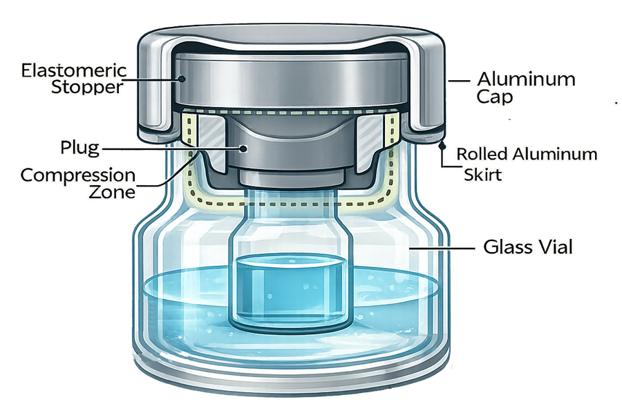
The diagram below illustrates the fundamental geometry of a properly seated elastomeric stopper within a vial finish. It highlights the plug region, radial compression interface, and aluminum crimp engagement that collectively form the sterile barrier.
2.2 Stopper Insertion Mechanics
During filling, stoppers are placed using vacuum or mechanical insertion systems. Key technical factors:
• Insertion force
• Stopper alignment
• Glass finish dimensional tolerance
• Line speed
Defects at this stage include:
• Tilted stopper – uneven compression around circumference
• High stopper – incomplete seating
• Stopper bounce – rebound after insertion
• Damaged plug – tearing or shaving
These defects directly affect subsequent crimp performance and long-term integrity.
2.3 Partial vs Full Stoppering
In lyophilization processes:
• Partial stoppering occurs prior to freeze drying
• Final seating occurs under vacuum or inert gas
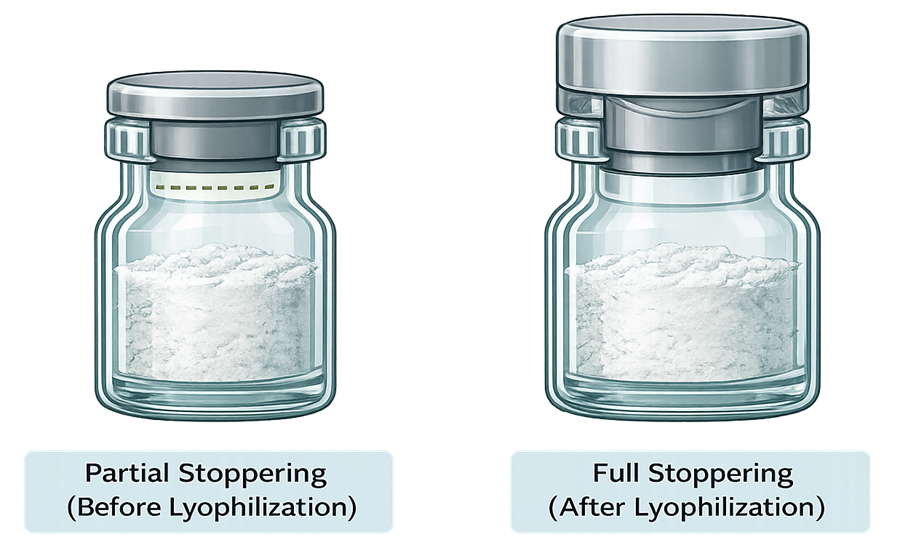
The illustration below compares partial stoppering prior to lyophilization with final full stoppering performed under vacuum or inert gas. It highlights the difference in stopper position, compression state, and final sterile barrier formation.
Risk factors include:
• Misalignment during transfer
• Inconsistent final compression depth
• Stopper drag due to vial neck variation
Full seating must be verified during qualification to ensure uniform compression across the batch.
3. Capping and Crimping Systems
3.1 Aluminum Seal Components
A typical vial closure includes:
• Aluminum skirt
• Center disc (often removable)
• Coated interior surface
Seal performance depends on proper roll formation around the vial finish and controlled downward force applied to the stopper.
3.2 Crimp Head Mechanics
Crimping systems apply radial force via rotating rollers. Critical mechanical aspects include:
• Roller geometry
• Chuck alignment
• Vertical force control
• Head synchronization
Improper setup leads to non-uniform skirt formation or excessive glass stress.
3.3 Crimp Geometry and Control
Key measurable parameters:
- Crimp diameter
- Roll depth
- Skirt curl
- Vertical compression displacement
The following table summarizes the primary geometric parameters used to evaluate crimp formation and stopper compression. These measurements define the mechanical envelope within which a sterile barrier is reliably formed. Each parameter is directly linked to seal integrity, retention strength, and long-term performance of the container–closure system.
| Parameter | Description | Importance |
|---|---|---|
| Crimp Diameter | The measured external diameter of the aluminum skirt after crimp formation around the vial finish. | Defines radial compression applied to the stopper and retention force under the vial bead. Excess diameter indicates under-crimp; reduced diameter may indicate over-compression and glass stress. |
| Roll Depth | The vertical distance from the top of the aluminum cap to the lowest point of the rolled skirt beneath the vial bead. | Determines mechanical engagement of the aluminum skirt under the glass finish. Insufficient roll depth reduces retention; excessive roll depth increases skirt stress and risk of cracking. |
| Skirt Curl | The inward curvature and profile of the bottom edge of the aluminum skirt after roll formation. | Ensures uniform skirt contact and proper engagement under the vial bead. Irregular curl may indicate tooling wear or misalignment and can lead to seal rotation. |
| Compression Displacement | The vertical displacement applied to the stopper during sealing, measured as downward movement from initial placement to final crimped position. | Indicates axial compression of the elastomeric stopper. Too little displacement results in insufficient sealing force; excessive displacement may cause stopper distortion or long-term relaxation. |
Defects include mechanical deviations from the validated crimp geometry or stopper compression envelope. These deviations may not be visually obvious yet can significantly compromise sterile barrier performance. Common crimp-related defects include:
- Under-crimp – Crimp diameter above the validated upper limit, indicating insufficient radial compression. This may result in inadequate skirt engagement and reduced retention force.
- Over-crimp – Crimp diameter below the validated lower limit, reflecting excessive radial force. This condition can induce glass finish stress, stopper over-compression, or aluminum skirt fatigue.
- Insufficient roll depth – Incomplete skirt engagement beneath the vial bead, reducing mechanical lock and increasing risk of seal rotation or displacement.
- Excessive roll depth – Over-penetration of the skirt under the bead, potentially causing aluminum cracking or uneven compression distribution.
- Irregular skirt curl – Non-uniform curl profile caused by tooling misalignment or wear. This may result in asymmetric compression and variable retention strength.
- Excessive compression displacement – Over-compression of the stopper leading to elastomer distortion, creep, or long-term stress relaxation.
- Insufficient compression displacement – Inadequate axial load applied to the stopper, increasing risk of micro-gaps at the plug–glass interface.
Each defect mechanism must be evaluated not only for immediate mechanical appearance but also for its impact on long-term integrity, CCIT performance, and sterility assurance over shelf life.
Crimp diameter must correlate with validated compression range.
4. Critical Process Parameters
Stoppering and sealing are parameter-driven processes. Key variables:
• Stopper insertion force
• Compression depth
• Crimp diameter
• Roll depth
• Line speed
• Component dimensional tolerances
Parameter limits must be defined during OQ. PQ must confirm performance at worst-case boundaries. Line speed is particularly critical. At maximum validated throughput, insufficient seating time may increase high-stopper risk.
5. Equipment Qualification Strategy
Stoppering and sealing systems must be qualified with the same rigor applied to sterilization or filling processes. Mechanical seal formation is a critical control function directly affecting sterility assurance.
5.1 Installation Qualification
Installation Qualification verifies that the sealing system is correctly installed, configured, and integrated within the filling line.
IQ activities must confirm:
• Correct installation of crimp heads, chucks, rollers, and associated tooling in accordance with manufacturer specifications
• Proper mechanical alignment of crimp heads relative to vial transport path
• Verification of torque, vertical force, or compression monitoring devices where applicable
• Calibration status of sensors measuring crimp diameter, compression force, or displacement
• Verification of programmable logic controller configuration and alarm functionality
• Proper integration with filling line interlocks and reject systems
Tooling identification numbers and configuration settings must be documented. Replacement components must be traceable to approved specifications.
Mechanical setup tolerances, including roller spacing and chuck height, must be recorded as baseline reference values for lifecycle comparison.
5.2 Operational Qualification
Operational Qualification establishes validated operating ranges for parameters that directly influence seal integrity. OQ must define and challenge:
• Acceptable crimp diameter range, including upper and lower control limits
• Acceptable stopper compression window, expressed as measurable displacement or force
• Vertical sealing force limits
• Roll depth and skirt formation criteria
• Maximum validated line speed
• Minimum dwell time for stopper seating
Parameter ranges must be justified through experimental studies, not nominal vendor settings.
Worst-case conditions must be intentionally challenged. This includes:
• Maximum vial neck diameter within specification
• Minimum vial neck diameter within specification
• Maximum and minimum stopper plug dimensions
• Aluminum seal dimensional variability
Tolerance stack-up analysis must be performed to evaluate combined worst-case component conditions. Seal performance must remain acceptable at these boundaries.
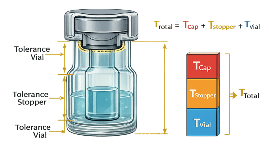
The diagram below illustrates the tolerance stack-up concept within a vial–stopper–seal system. Dimensional variation in the vial finish, elastomeric stopper, and aluminum seal combine to influence final compression and crimp geometry. The cumulative effect defines the mechanical sealing envelope that must remain within validated limits.
Data collection should include:
• Crimp diameter distribution analysis
• Stopper height measurement
• Compression displacement verification
• Glass damage inspection
OQ must establish documented parameter windows that are subsequently locked under change control.
5.3 Performance Qualification
Performance Qualification confirms that the validated parameter ranges consistently produce acceptable seal formation under routine production conditions. PQ must demonstrate:
• Consistent seal formation across full batch duration
• Representation of all active crimp heads and sealing stations
• Sampling from beginning, middle, and end of production run
• Operation at maximum validated line speed
• Inclusion of any format changeovers or maintenance events occurring during run
Mechanical seal quality must be evaluated through:
• Crimp diameter measurement
• Visual inspection for skirt defects
• Stopper seating verification
• Glass finish inspection
Most critically, PQ must include correlation with CCIT results. Mechanical parameter compliance must align with acceptable integrity outcomes. If CCIT failures or borderline results occur during PQ, root cause analysis must determine whether mechanical parameters, component variability, or equipment alignment contributed. PQ establishes that the mechanical sealing process, within defined operating limits, consistently creates a sterile barrier capable of passing validated integrity testing.
Qualification of stoppering and sealing systems defines the engineered boundary conditions under which sterile barrier formation is reliable. These limits become the basis for ongoing lifecycle control and change impact assessment.
6. Failure Modes and Defect Mechanisms
Seal defects are typically mechanical in origin. Common mechanisms include:
- Under-compression: Results in micro-gaps at stopper–glass interface.
- Over-compression: May cause elastomer creep or relaxation over time.
- Skirt cracking: Aluminum fatigue due to excessive roll depth or improper alloy.
- Stopper extrusion: Excess compression causing material displacement.
- Seal rotation: Indicates inadequate skirt engagement.
- Glass finish damage: Creates leak path independent of stopper compression.
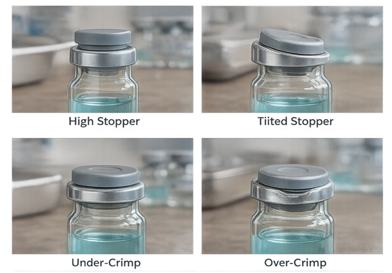
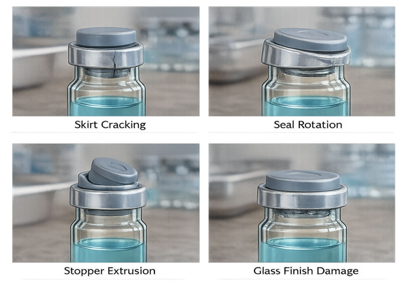
The illustration below presents primary mechanical defects resulting from improper stopper seating or incorrect crimp parameter settings.
The following illustration shows additional defect modes associated with material stress, tooling wear, and glass–seal interface damage.
Each failure mode must be understood in terms of mechanical cause and long-term sterility risk.
7. Integration with CCIT
Mechanical qualification defines the sealing envelope. CCIT verifies barrier outcome.
CCIT trending must be periodically correlated with:
• Crimp diameter distributions
• Stopper compression data
• Tooling wear history
• Preventive maintenance intervals
Mechanical drift often precedes measurable integrity failures.
8. Lifecycle Control
Seal formation is subject to mechanical wear and component variability.
Lifecycle oversight must include:
• Crimp head maintenance scheduling
• Roller wear inspection
• Compression monitoring
• Periodic dimensional verification
• Change control impact assessment
9. Revalidation Triggers
Requalification may be required following:
• Stopper formulation change
• Aluminum seal specification change
• Glass supplier change
• Crimp tooling replacement
• Sustained CCIT borderline results
• Process parameter drift outside validated range
Stoppering and sealing systems represent the engineered formation of the sterile barrier. Their control must be as structured and defensible as any sterilization process.