
Tank and Process Vessel Cleaning Integration
1. Introduction
Pharmaceutical tanks and process vessels must be designed to allow effective cleaning between manufacturing operations. Proper cleaning integration ensures removal of product residues, prevents cross-contamination, and supports compliance with Good Manufacturing Practice requirements.
Cleaning systems must be incorporated into the vessel design to ensure that all internal surfaces can be reached by cleaning solutions and that residues can be fully removed during cleaning cycles. Integration of cleaning systems also allows cleaning operations to be automated, controlled, and reproducible.
Most pharmaceutical vessels are cleaned using Clean-in-Place (CIP) systems that circulate cleaning solutions through the equipment without requiring disassembly. Proper integration of CIP systems is therefore an important aspect of vessel design and operation.
2. Cleaning Strategy for Tanks and Process Vessels
The cleaning strategy for process vessels depends on the type of product processed, the degree of contamination risk, and regulatory requirements. Cleaning strategies must ensure removal of residues that could affect product quality or lead to cross-contamination. Typical cleaning strategies include:
• automated Clean-in-Place systems
• manual cleaning for small or portable vessels
• combination of CIP and manual cleaning for complex equipment
Cleaning procedures must be capable of removing product residues, cleaning agents, and potential contaminants from all internal surfaces of the vessel. Cleaning strategies must also consider compatibility with vessel materials and process conditions.
Cleaning integration should therefore be considered during equipment design to ensure that cleaning operations can be performed efficiently and consistently.
3. Clean-in-Place System Architecture
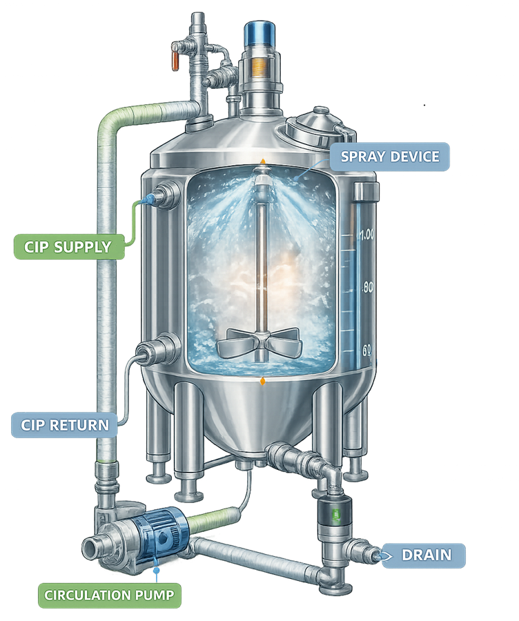
Clean-in-Place systems are commonly used in pharmaceutical manufacturing to clean process vessels without disassembling the equipment. CIP systems circulate cleaning solutions through the vessel and associated piping while spray devices distribute the cleaning fluid across internal surfaces. Typical CIP system components include:
• cleaning solution supply lines
• circulation pumps
• spray devices such as spray balls or rotary spray heads
• return piping for cleaning solution recovery
• valves and control systems
CIP systems may operate as single-use cleaning circuits or as recirculating systems where cleaning solution is reused during a cleaning cycle. Control systems regulate parameters such as flow rate, temperature, cleaning solution concentration, and cleaning cycle duration.
Proper CIP integration ensures that cleaning solutions reach all surfaces of the vessel and associated piping. The illustration shows a typical clean-in-place system integrated with a pharmaceutical process vessel. The diagram highlights the main CIP supply and return paths used during automated cleaning operations.
4. Spray Device Types and Placement
Spray devices play a critical role in distributing cleaning solutions inside process vessels. These devices are installed inside the vessel and direct jets of cleaning solution onto internal surfaces during clean-in-place operations. Effective distribution of the cleaning solution ensures that all product-contact surfaces are exposed to sufficient mechanical action and chemical contact during the cleaning cycle. Common spray device types include:
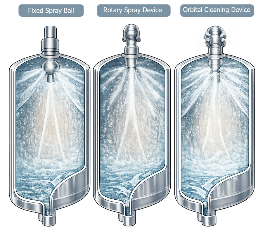
- fixed spray balls, stationary devices containing multiple perforations that discharge cleaning solution in predetermined directions. The spray pattern remains constant during operation, and cleaning relies primarily on liquid distribution and chemical action that forms a wetting film over vessel surfaces. Because of their simple design and absence of moving parts, fixed spray balls are commonly used in smaller vessels or applications with relatively simple geometry.
- rotary spray heads, which rotate during operation to produce a dynamic spray pattern that sweeps across the vessel interior. The rotating motion distributes cleaning jets over a larger surface area and provides greater mechanical impact than fixed spray balls, improving removal of more difficult residues.
- orbital cleaning devices, which generate high mechanical cleaning action through controlled rotating or orbital jet patterns that deliver concentrated impact across vessel surfaces. These devices are typically used in large vessels, systems with complex internal structures, or applications involving viscous or difficult-to-remove products.
The illustration highlights the difference between the stationary spray distribution of fixed spray balls, the rotating coverage pattern of rotary spray devices, and the high-impact orbital jet action produced by orbital cleaning devices.
Proper placement of spray devices is essential to ensure that all internal surfaces are exposed to cleaning solution. The number and location of spray devices depend on vessel size, vessel geometry, and the presence of internal components such as agitators, dip tubes, or baffles that may create shadowed areas.
During equipment qualification, spray coverage testing is typically performed to verify that the installed spray devices adequately wet all internal surfaces of the vessel. One widely used method is riboflavin coverage testing, in which a fluorescent riboflavin solution is applied to internal surfaces of the vessel prior to the cleaning cycle. After the CIP cycle is executed, the vessel interior is inspected under ultraviolet light. Areas where the riboflavin has been removed indicate effective spray coverage, while any remaining fluorescence identifies potential areas of insufficient cleaning coverage. These tests help confirm that spray device placement, flow rate, and spray patterns provide adequate cleaning coverage across the entire vessel interior.
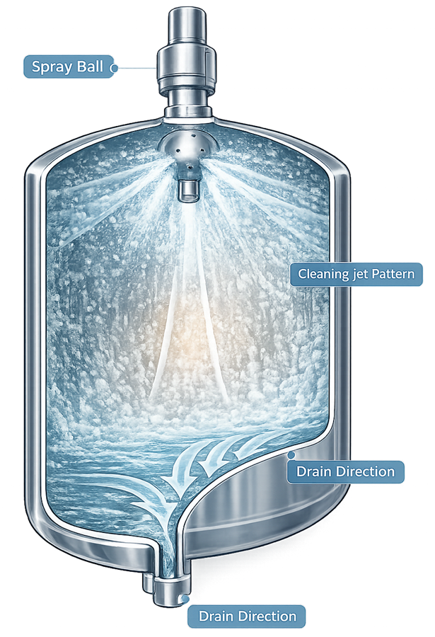
The illustration shows the distribution of cleaning solution inside a process vessel during a clean-in-place cycle. Cleaning solution is discharged from the spray device, impacts the vessel walls, and flows downward across the internal surfaces toward the bottom outlet, illustrating the mechanism by which spray devices distribute cleaning solution to remove product residues.
5. Cleaning Parameter Control
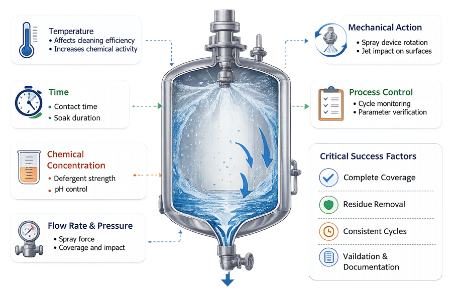
Effective cleaning requires control of several critical parameters. Cleaning performance depends on the interaction of chemical, thermal, mechanical, and time factors. Key cleaning parameters include:
• cleaning solution concentration
• cleaning temperature
• flow rate and spray pressure
• cleaning cycle duration
These parameters are typically controlled through automated CIP control systems that monitor and regulate the cleaning process. Maintaining consistent cleaning parameters ensures reproducible cleaning performance and supports cleaning validation activities.
The illustration shows the key parameters monitored during automated cleaning cycles in pharmaceutical process vessels.
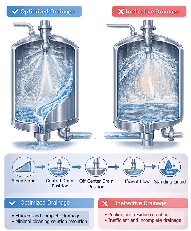
6. Drainage and Residue Removal
Effective drainage is an important design requirement for cleanable vessels. After cleaning cycles are completed, cleaning solutions and residues must be fully removed from the vessel.
Vessel geometry plays a key role in drainage performance. Conical or sloped vessel bottoms allow liquids to flow toward the bottom outlet valve, reducing the risk of stagnant liquid remaining in the vessel. Proper drainage supports:
• complete removal of cleaning solutions
• prevention of residue accumulation
• improved drying of vessel surfaces after cleaning
Drainage performance is typically evaluated during equipment qualification and cleaning validation activities. The illustration shows how vessel geometry promotes removal of cleaning solutions during CIP operations.
7. Cleaning Verification and Validation
Cleaning processes must be verified to demonstrate that product residues, cleaning agents, and potential contaminants are effectively removed from the vessel after cleaning operations. Verification activities confirm that cleaning performance meets predefined acceptance criteria and that the equipment is suitable for subsequent manufacturing use.
Cleaning verification typically combines visual inspection and analytical sampling methods to evaluate the effectiveness of the cleaning process. Visual inspection is performed after completion of the cleaning cycle to confirm that vessel surfaces are free from visible residues, films, or particulate contamination.
Analytical verification commonly includes the following sampling approaches:
• visual inspection of vessel surfaces to confirm absence of visible residues
• swab sampling of product-contact surfaces
• rinse sampling of cleaning solutions
Swab sampling is performed by wiping a defined surface area of the vessel interior using a validated sampling swab. The swab is typically moistened with a suitable solvent and applied to selected worst-case locations such as weld seams, vessel walls, gaskets, agitator blades, or valve seats. The swabbed material is then transferred to a laboratory vial and analyzed for potential residues.
Rinse sampling involves collecting samples of the final rinse solution discharged from the vessel during the cleaning cycle. These samples represent residues that may remain on vessel surfaces and are carried out of the equipment by the rinse solution. Rinse samples are typically collected from the vessel drain or CIP return line and transferred to laboratory vials for analytical testing.
Cleaning validation studies are performed to demonstrate that cleaning procedures consistently remove residues to acceptable levels. Validation protocols typically define sampling locations, analytical methods, residue limits, and acceptance criteria. The results of these studies provide documented evidence that the cleaning process is effective and reproducible.
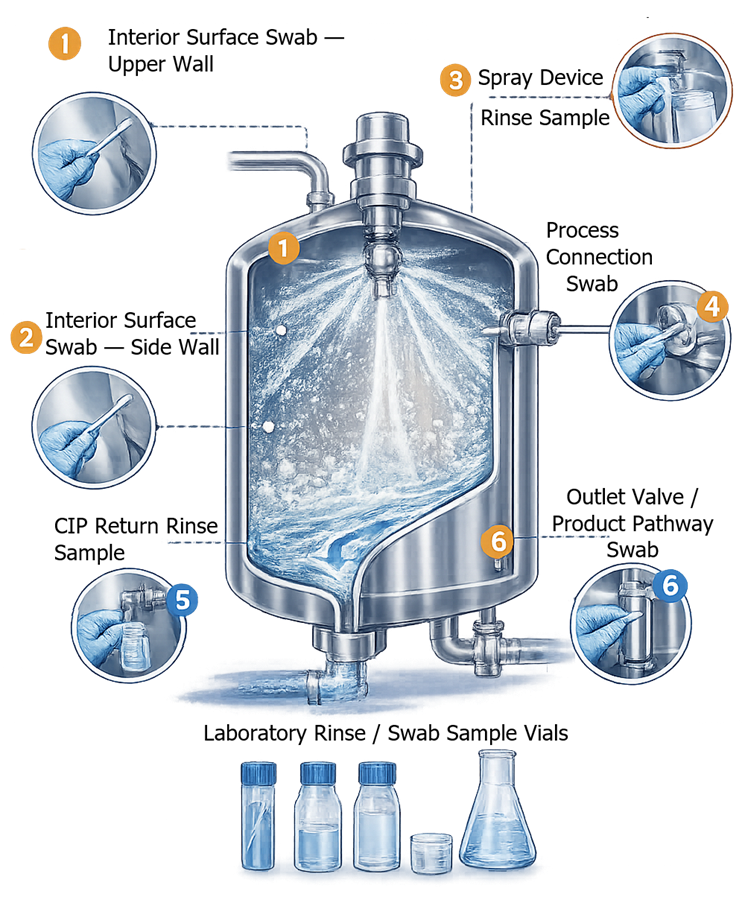
The illustration shows typical sampling locations used during cleaning verification of pharmaceutical process vessels, including interior surface swab locations, spray device sampling points, process connection areas, and rinse sampling points collected from the vessel outlet or CIP return line.
8. Integration with Process Controls
Cleaning systems used in pharmaceutical manufacturing are typically integrated with facility automation and process control platforms to ensure that cleaning cycles are executed in a controlled, repeatable, and well-documented manner. Automated control systems reduce operator variability and ensure that all critical cleaning parameters remain within validated operating limits. Integration with control systems also provides traceable electronic records demonstrating that cleaning operations were executed according to defined procedures.
8.1 Control System Architecture
Clean-in-Place systems are normally connected to a programmable logic controller that manages the operation of pumps, valves, heating systems, and chemical dosing components. The PLC executes predefined cleaning sequences based on programmed logic and stored cycle recipes. Operators interact with the control system through a human–machine interface. From this interface the operator can:
- select the appropriate cleaning recipe
- initiate or terminate a cleaning cycle
- monitor system status during operation
- review alarms and system notifications
Once a cleaning cycle is initiated, the control system automatically performs each step of the sequence according to the programmed logic. Typical automated steps include:
- pre-rinse cycles
- detergent circulation
- intermediate rinsing
- final rinse and verification steps
Automation ensures that the correct sequence, timing, and process conditions are maintained during each cleaning cycle.
8.2 Monitoring of Critical Cleaning Parameters
During execution of the cleaning cycle, the control system continuously monitors critical process parameters to confirm that cleaning conditions remain within validated limits. Sensors installed in the CIP skid and associated piping transmit real-time measurements to the control system. Commonly monitored parameters include:
- solution temperature
- flow rate through the cleaning circuit
- system pressure
- conductivity of rinse water
- cleaning cycle duration
The control system compares measured values to predefined acceptance limits defined during cleaning validation. If process conditions move outside the acceptable operating range, the system generates alarms and may interrupt the cycle depending on configured control logic.
8.3 Alarm Handling and Safety Interlocks
Alarm management and safety interlocks are implemented within the control system to prevent unsafe or incorrect operating conditions during cleaning operations. Typical alarm conditions include:
- insufficient cleaning solution flow
- incorrect solution temperature
- pump or valve malfunction
- failure of instrumentation signals
When an alarm condition occurs, the system may perform one or more of the following actions:
- notify the operator through the HMI interface
- pause the cleaning sequence
- terminate the cleaning cycle
- prevent progression to the next step until the condition is resolved
Safety interlocks are also implemented to protect equipment and product integrity. These interlocks may prevent:
- process equipment operation during active cleaning cycles
- simultaneous routing of cleaning chemicals into product transfer lines
- operation of pumps or valves under unsafe conditions
Such safeguards reduce the risk of equipment damage and cross-contamination.
8.4 Data Recording and Electronic Documentation
Integration with process control systems allows automatic recording of cleaning process data. Control platforms typically store operational data in historian databases, electronic batch records, or supervisory control systems. Recorded information may include:
- cleaning cycle start and completion times
- parameter values during the cycle
- alarm events and system responses
- operator actions and acknowledgements
These electronic records provide traceable documentation demonstrating that the cleaning cycle was executed according to the validated procedure.
8.5 Regulatory and Validation Considerations
Control system integration supports compliance with regulatory expectations for pharmaceutical manufacturing. Automated monitoring, alarm management, and electronic data recording provide objective evidence that cleaning cycles operate within validated parameters. During qualification and validation activities, testing typically confirms:
- correct execution of automated cleaning sequences
- proper response to alarm conditions
- accuracy and reliability of instrumentation signals
- integrity and traceability of recorded cleaning data
Verification of these functions demonstrates that the cleaning control system reliably supports validated cleaning operations and provides the documentation required for regulatory compliance.